Posts Tagged cave
Climbing Taiwan Removable Bolts Review
Posted by Bill Storage in Engineering & Applied Physics on November 6, 2025
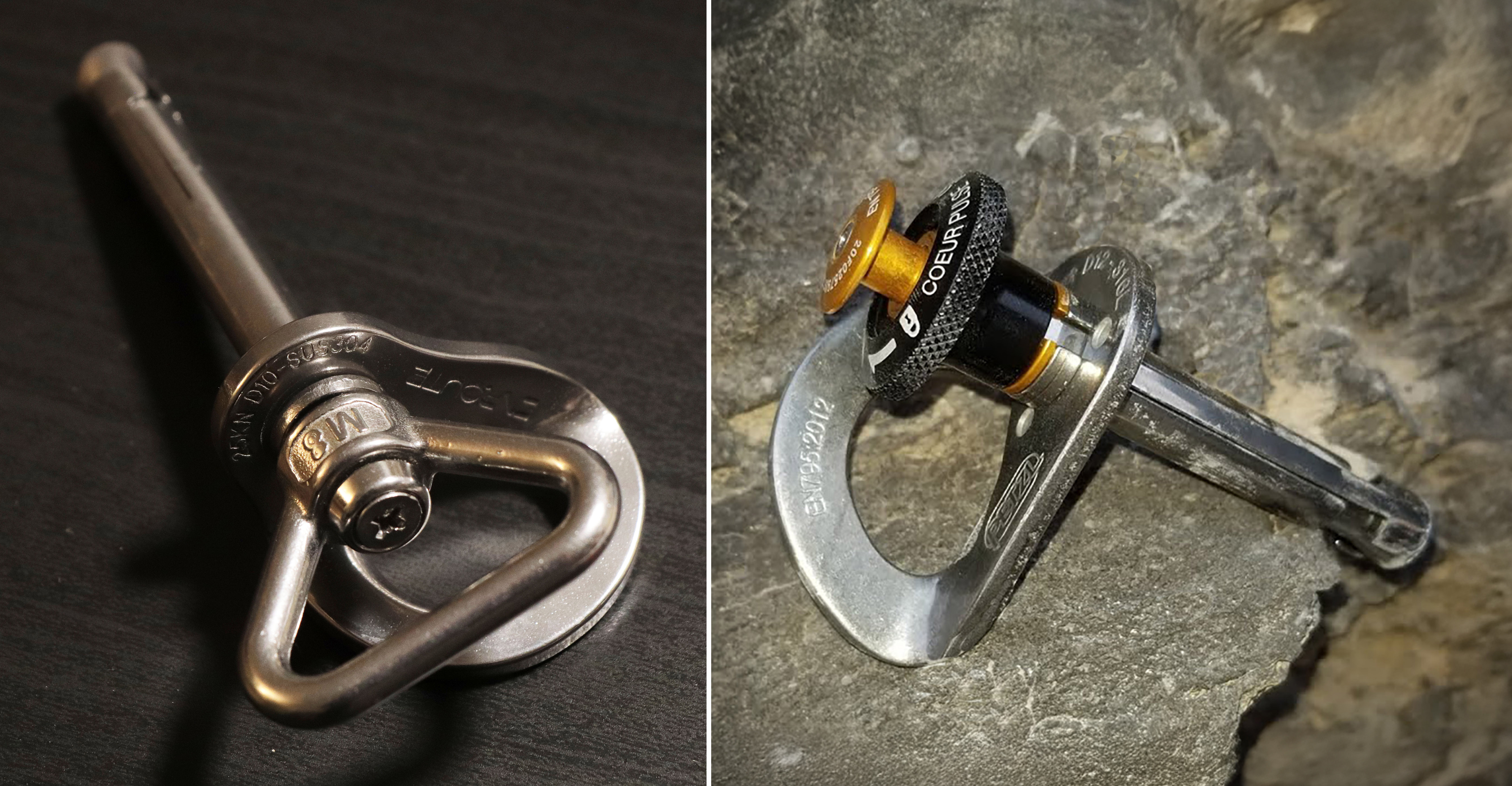
Friends and I have been experimenting with removable bolts in muddy caves, and many of us have been concerned about the robustness of the devices. I don’t mean their strength. They’re plenty strong. I mean how well do they hold up in a cave environment – and can we be ensured of a good placement. I just got some new removable bolts from Climbing Taiwan (CT). Compared to the Petzl Pulse design, which have proven to be finicky in caves, they look like they might be better suited for use in cave environments.
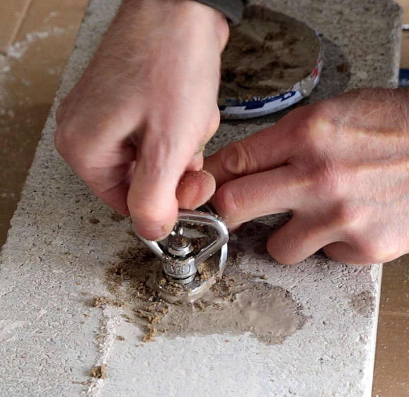
I don’t have a cave or a hammer drill on hand right now, so I put a 10mm masonry bit in my handheld driver and drilled holes in a concrete block to test the bolts.
For this testing I wanted to drill the hole barely long enough to fit the bolt in – against the recommendations of the manufacturer. I wanted to experiment with the consequences of crud in the bottom of the hole.
Normally, with 3/8 and 10mm bolts wedge bolts wedge bolts I don’t blow out the holes or brush them underground. I merely withdraw the drill with it rotating slightly and pull the dust out of the hole. I’ve placed hundreds of bolts and have never had a spinner. I torque my 3/8 wedge bolts to 25 foot pounds underground.
Because, for these tests, I am drilling vertically downward and I am using a masonry bit instead of a hammer drill bit, I had to brush the dust out of these holes. I did not use a blow tube. This is really bad bolting hygiene. I wanted to see if I could gum up the works. I am intentionally using these removable bolts wrong, against the advice of the manufacturer, and against good sense.
To simulate the abuse that bolts take underground, I first mixed the concrete dust with water and packed it onto the bolt mechanism. Then I poured the sludge into the hole.
Then I added sand to the mix. I packed on as much sand as I could. I also tried getting sand into the threads at the top of the hanger. This proved no problem for installation or removal. I then pushed sand into the hole to see if I could force the wedge through the sand sludge and back toward the outside of the hole.
For the next simulation of cave mud I combined honey and cornstarch. Wet corn starch is fun to use in these experiments because it is a non-euclidean fluid with some odd properties. I again added sand. I then smeared the cornstarch honey sand combination along the sleeve and the threaded region.
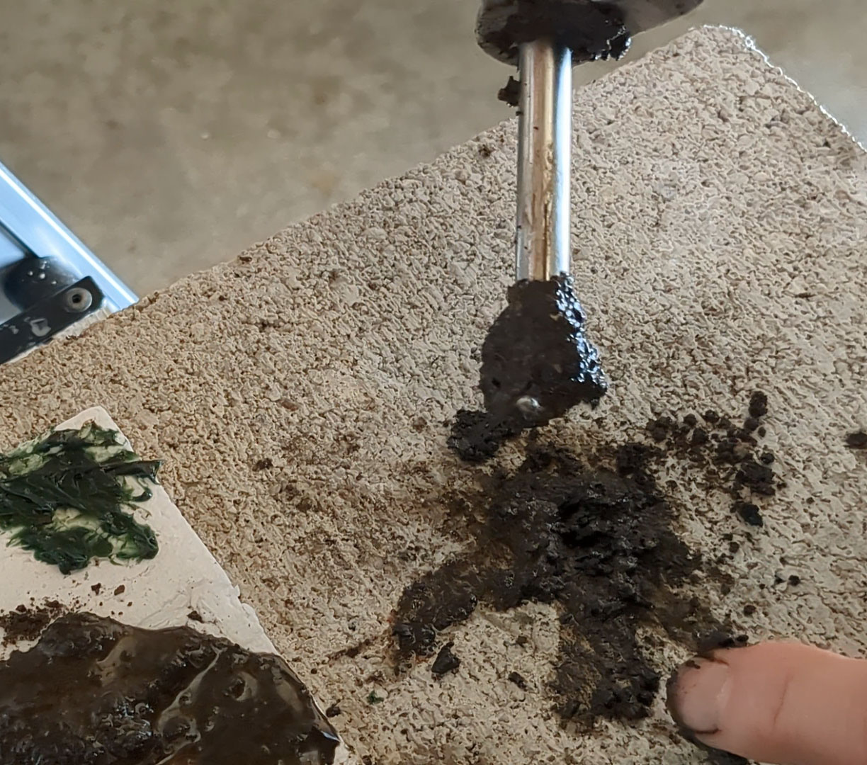
For the next test I got a fresh cylinder of clay- rich mud and added it to the mix. The bolt and the sludge clearly filled the entire hole as is visible by the overflow. I did the same with a mix of plumber’s grease and garden dirt. Again, no problem.
I used a pressure washer to clean them. I took them apart to be sure. Good as new.
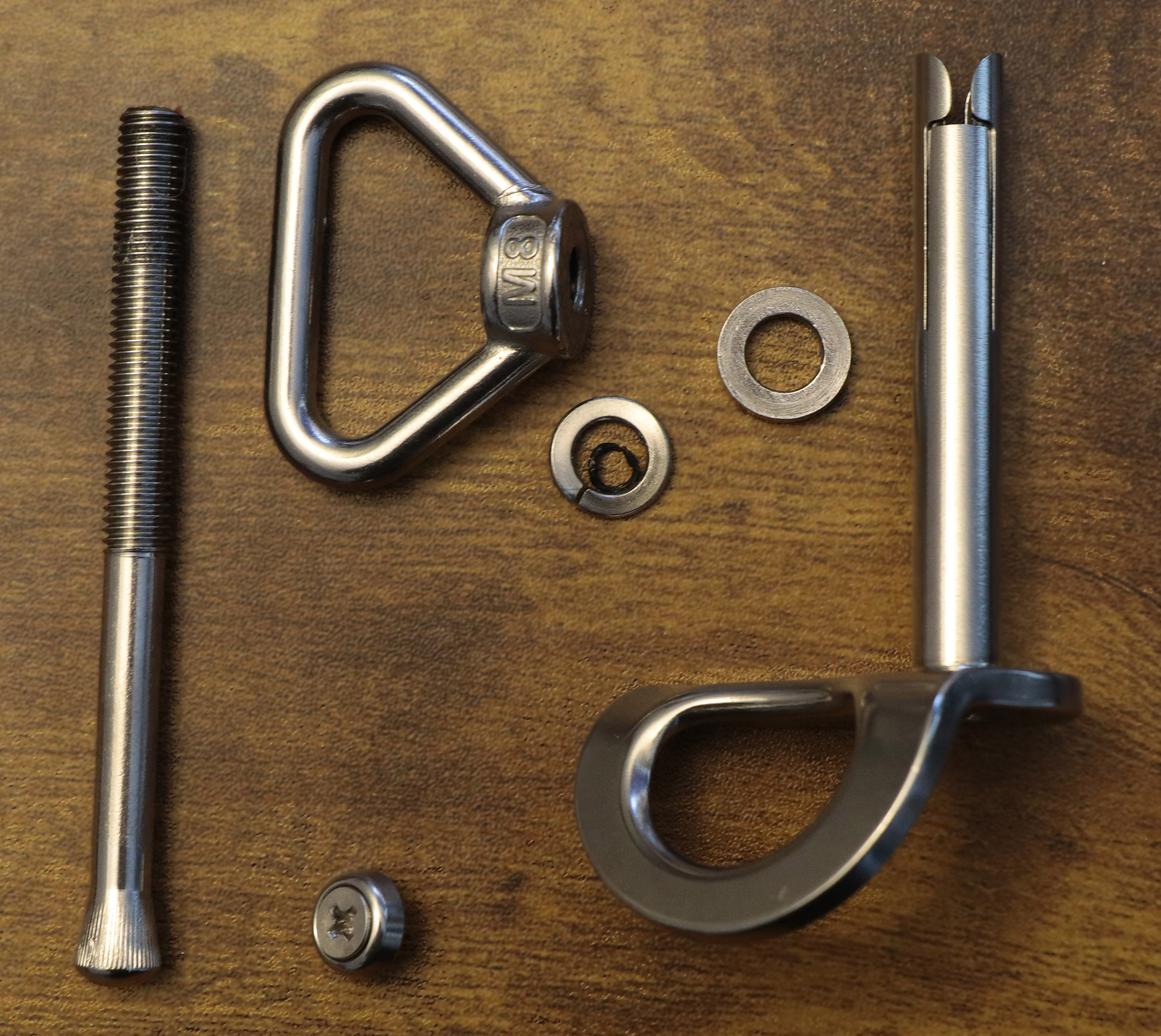
The manufacturer says they used 2205 stainless steel for the threaded shaft and 304 for everything else. These are smart choices that reflect sound engineering. 304 is very widely used. It’s machinable and has high ductility. Its ultimate strength is several times higher than its yield strength. It is extremely forgiving and has excellent corrosion resistance. Duplex 2205 is much stronger, much more expensive, and has some trade-offs (like weldability), none of which are at all relevant to this usage.
I tested the components for ferromagnetism. In theory, 304 alloy hangers should not be magnetic. OK, little bit of engineering here. 304 is austenitic; its atoms are arranged in a body-centered cubic structure. But when you cut or beat on austenitic stainless, you can cause some degree of room-temperature phase transformation. A room-temperature crystalline phase change always seemed like magic to me, but it happens. Ancient blacksmiths were similarly amazed. This cold-working causes atoms to jump into a body-centered tetragon pattern called martensite, which is magnetic. It also causes carbon atoms to bunch up a bit, and this can reduce corrosion life.
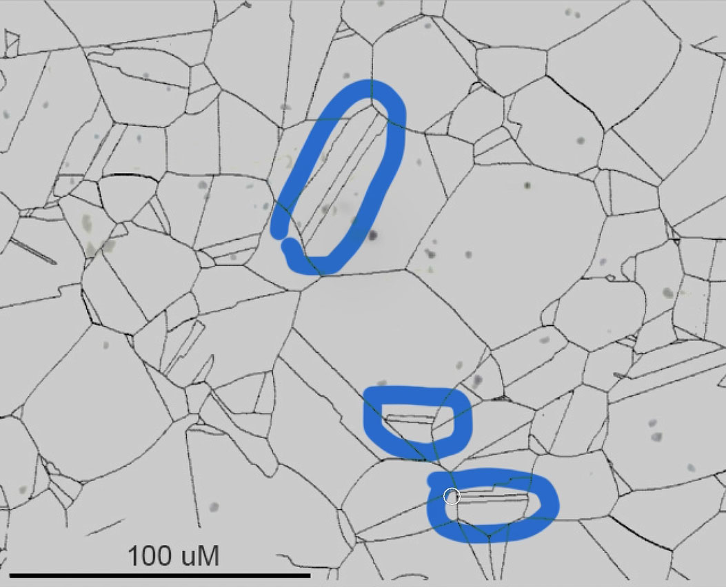
But these bolts are not intended as permanent anchors. And when I look at the hangers under a scope at 250x, I see maybe a couple of percent martensite. Rough calculation of the life of a 304 bolt in a typical Appalachian cave with no brine and low chlorides yields a range of about 1000 to 20,000 years. If we shift that bolt into its martensitic state, we’d reduce its life in a cave down to maybe 50 to 1,000 years. But that is for full martensite, and I’m seeing only a percent or two. In other words, we can ignore the fact that this hanger is slightly magnetic. The Duplex 2205 threaded shaft (“duplex” because it is part ferrite, part austenite – elongated austenite grains in a ferritic matrix, so it is magnetic), since it isn’t welded or otherwise altered, would have a corrosion life of 2 to 5 times that of 304.
I measured hardness at Rockwell C25 – around 90,000 psi – a bit higher than you’d expect for annealed 304, but consistent with the cold working that resulted in the magnetism. Totally inconsequential.
I generally don’t do destructive testing. It’s usually pointless or worse. It’s entertaining to watch gear break, but focusing on ultimate strength just encourages dangerous misconceptions. Safety in climbing gear depends on how forces are distributed, how materials deform, and, mostly, how elasticity affects the system – how energy is absorbed. The inelasticity of a static rope that’s stronger than a dynamic rope can kill you. F=ma and F=kx are not just equations – they are life-and-death considerations.
I like to look at the underlying physics, and highlight what matters in practical use. My goal is to give climbers accurate, responsible insight – not spectacle – and to counter the intuition that ‘stronger = safer.’ This approach is personal to me as well: a close friend died while aid climbing in a cave because he misunderstood these principles. We might honor his memory by helping others understand how stuff works.
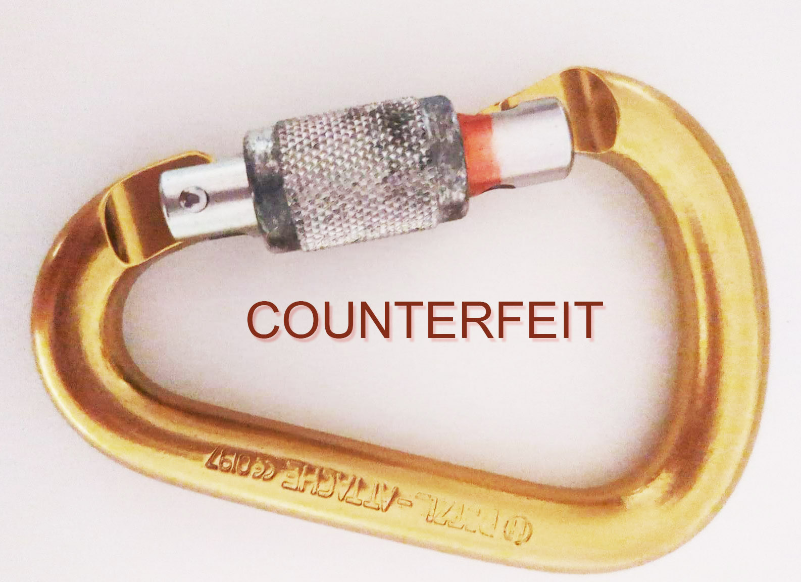
Why not break them? The removable-bolt components – bolts and hangers – are made from standard engineering materials, like 304. These materials are mass-produced in sheet and rod form, and have extremely low likelihood of defects. 304 stainless is not a cottage-industry alloy. Producing it requires integrated melt, alloying, and forging infrastructure with tight control of composition and processing. You can’t fake it cheaply. So the global quality variation for 304 is extremely narrow compared to, say, low-alloy steels, bronze, or, unfortunately for cavers, aluminum castings and forgings. Counterfeit carabiners. But that’s another article.
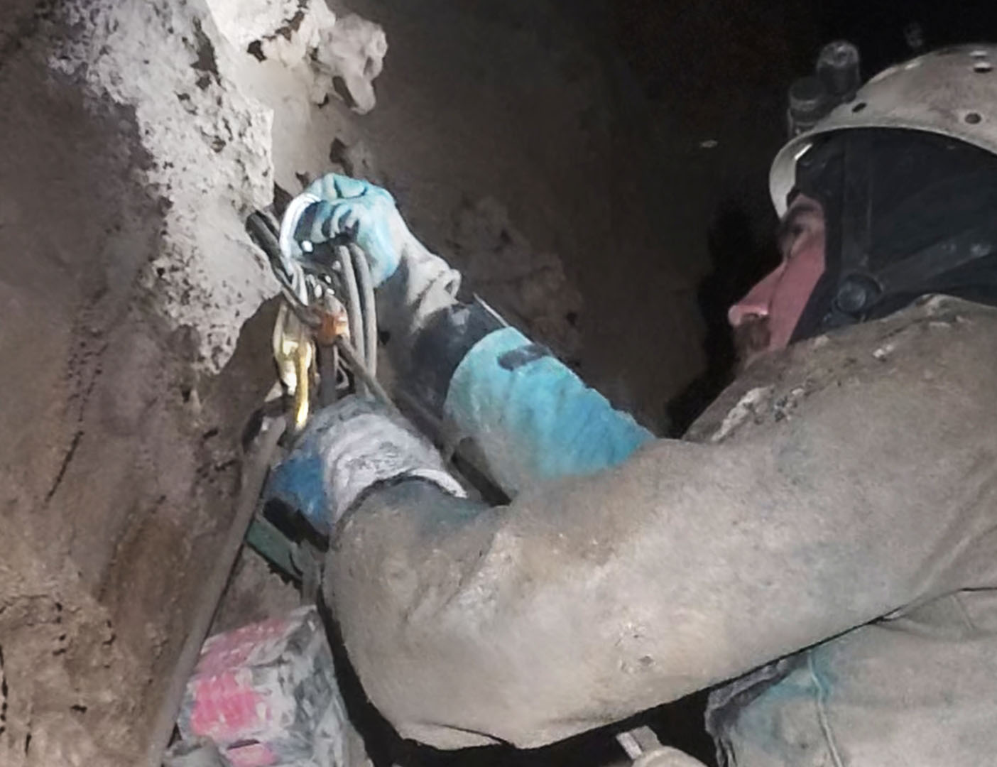
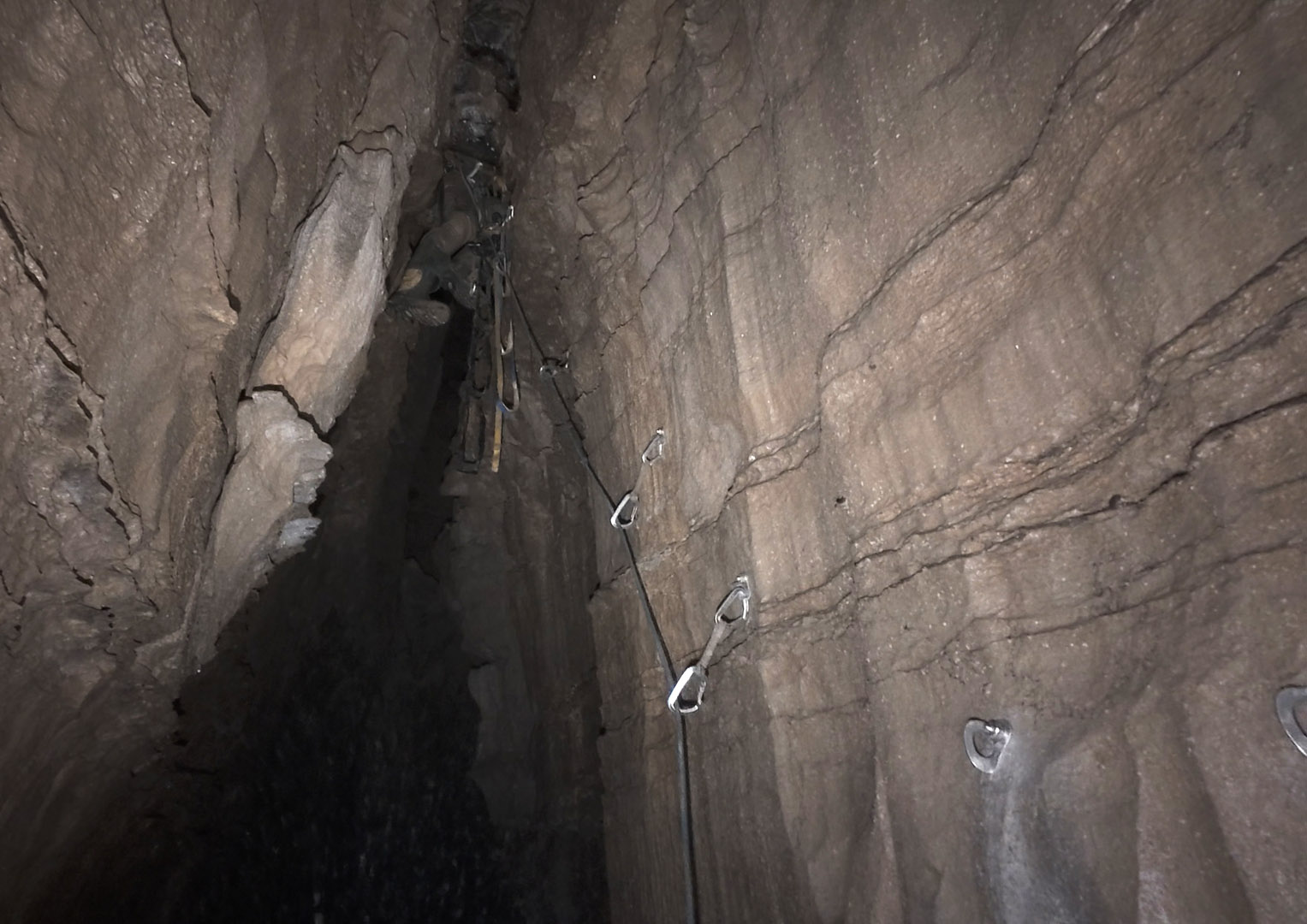
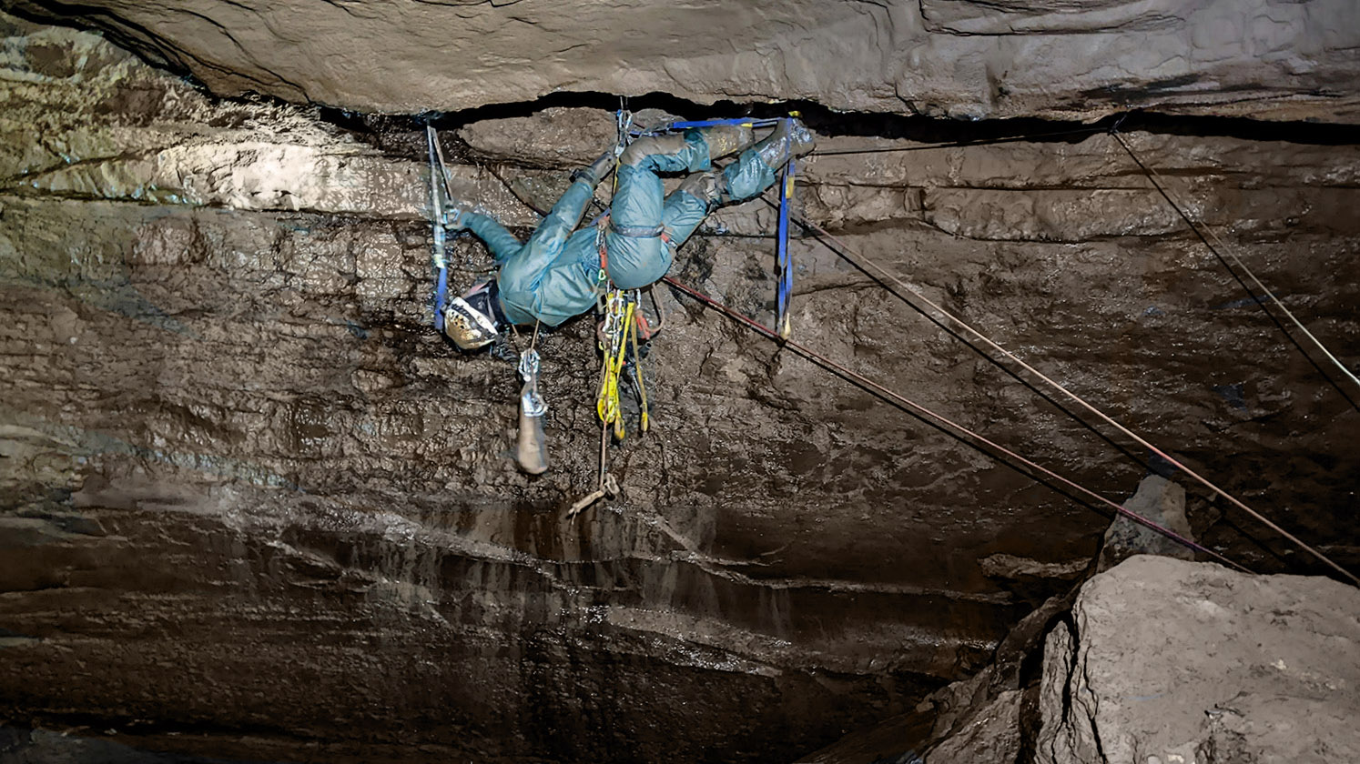
Breaking these bolts on video would add zero real information. Their strength far exceeds what a human body can impose or withstand. What actually matters – the rock quality, technique, and proper installation – is rarely tested or demonstrated on YouTube. If there is concern about a manufacturer’s integrity, destructive testing of one or two bolts is meaningless. Instead, careful microstructural examination and non-destructive testing across a larger sample set provide meaningful insight, without teaching viewers some sort of cargo-cult science. Removable bolts are intended for shear loading only. Think standard aid climbs, not ones like this:
But any real-world usage involves some amount of axial load. Tests on other removable bolts show them to have very high strength in the axial direction. Usually, the rock blows out first.
The fact that the rock usually blows out first points to another advantage of these Climbing Taiwan bolts over the Petzl. In soft rock, bolt length trumps bolt diameter because rock strength dominates. The 3-inch, 10mm diameter CT bolt vs. the 2 and a quarter inch Petzl 12mm. In hard rock, bolt strength dominates, but in hard rock, the breaking strength for both 10 and 12mm far exceed survivability. This is a perfect example of where destructive testing results will lead you to the wrong conclusion.
With a few assumptions, we can easily calculate the relative performance of the Pulse and the CT bolts loaded in shear:
Sleeve / shaft sizes
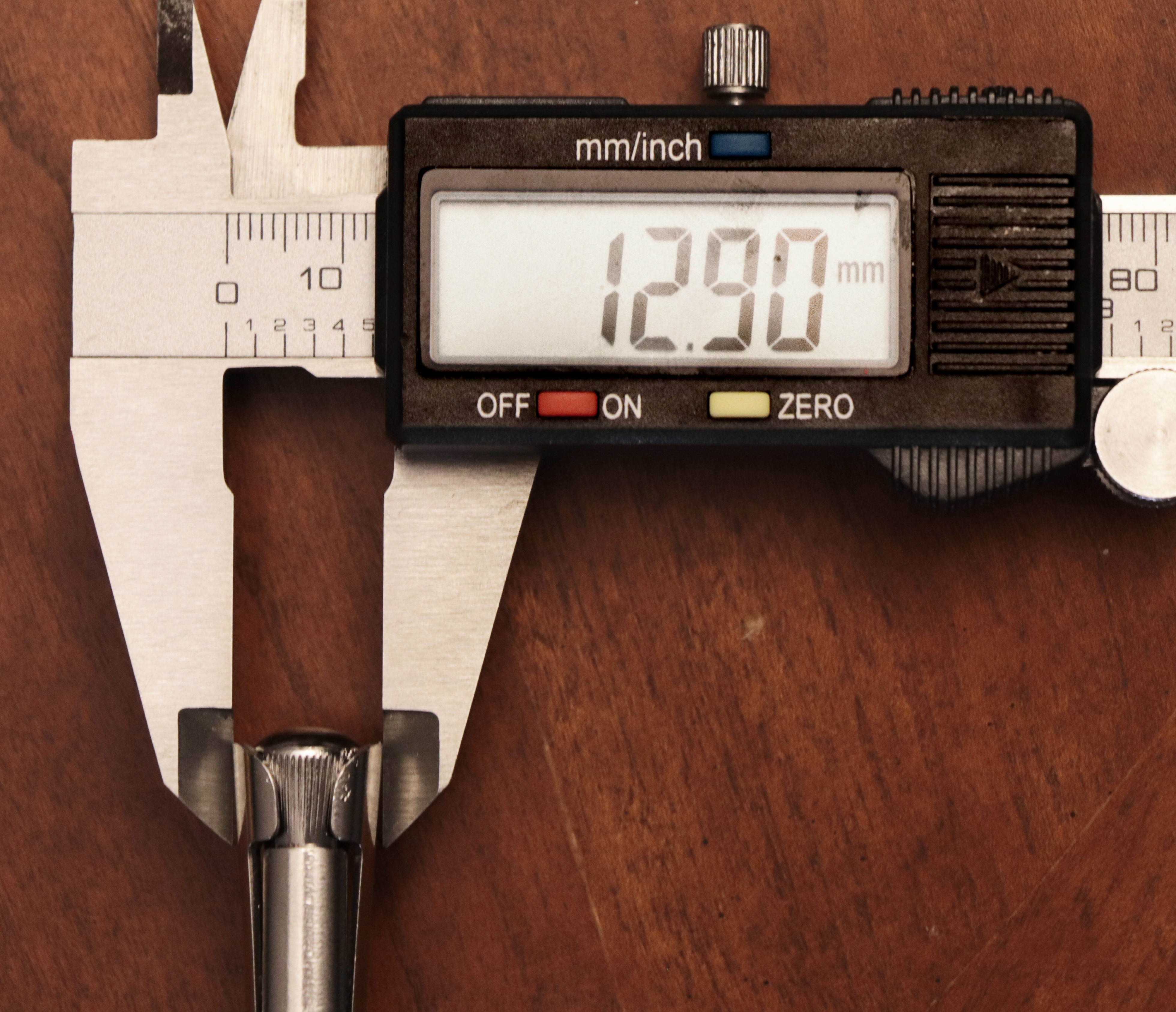
- Pulse: sleeve Ø = 12.0 mm, shaft Ø = 10.0 mm, embed length = 55 mm
- CT (10 mm): sleeve Ø = 10.0 mm, shaft Ø = 8.0 mm, embed length = 77 mm.
- Material strengths (conservative working numbers)
- Sleeve material 304 stainless, UTS = 520 MPa. Shear strength = 0.6·UTS = 312 MPa.
- Shaft material 2205 duplex, UTS = 860 MPa. Shear strength = 0.6·UTS = 516 MPa.
- Use the shaft shear (2205) as the bolt shear limit.
- Two limiting modes considered, and the lower one governs:
For rock-limited shear:
Rock shear strength × lateral contact area of the sleeve (projected cylindrical area = π·d_sleeve·embed_length). This models shear/punching or interface shear of the sleeve against rock.
For bolt (shaft) shear:
Material shear strength × cross-sectional area of the shaft (π·d^2/4). This models a straight shear through the shaft.
No complex friction, bending, or stress concentrations included. This is a first-order, worst-case shear capacity comparison.
| Rock shear strength | Pulse 12 mm, embed 55 mm | CT 10 mm, embed 77 mm |
| 1000 psi | rock limit 14.30 kN (3,214 lb) bolt limit 40.53 kN (9,111 lb) | rock limit 16.68 kN (3,761 lb) bolt limit 25.94 kN (5,831 lb) |
| 2000 psi | rock limit 28.59 kN (6,428 lb) bolt limit 40.53 kN (9,111 lb) | rock limit 33.36 kN (7,523 lb) bolt limit 25.94 kN (5,831 lb) |
| 4000 psi | rock limit 57.18 kN (12,855 lb) bolt limit 40.53 kN (9,111 lb) | rock limit 66.71 kN (14,998 lb) bolt limit 25.94 kN (5,831 lb) |
To evaluate the sensitivity of this model to assumptions, we can make the following changes, aiming at higher conservatism:
- 2205 duplex shear taken as 0.5·UTS, i.e. 430 MPa.
- A conservative Rock-punching reduction factor of 0.6 applied to the nominal rock shear strength to model local failure modes, stress concentrations, and imperfect contact.
| Rock shear strength | Pulse 12 mm, embed 55 mm | CT 10 mm, embed 77 mm |
| 1000 psi | rock limit 8.58 kN (1,928 lb) bolt limit 33.77 kN (7,592 lb) | rock limit 10.01 kN (2,250 lb) bolt limit 21.61 kN (4,859 lb) |
| 2000 psi | rock limit 17.16 kN (3,857 lb) bolt limit 33.77 kN (7,592 lb) | rock limit 20.01 kN (4,499 lb)bolt limit 21.61 kN (4,859 lb) |
| 4000 psi | rock limit 34.31 kN (7,713 lb) bolt limit 33.77 kN (7,592 lb) | rock limit 40.03 kN (8,999 lb) bolt limit 21.61 kN (4,859 lb) |
This results in lower strength values for both rock and bolt, but the relationships and conclusions still stand. In weak rock, length trumps diameter; in strong rock, bolt strength dominates but both 10 and 12mm strengths are far above survivability. The below chart plots governing capacity vs nominal rock shear to show the crossover points:
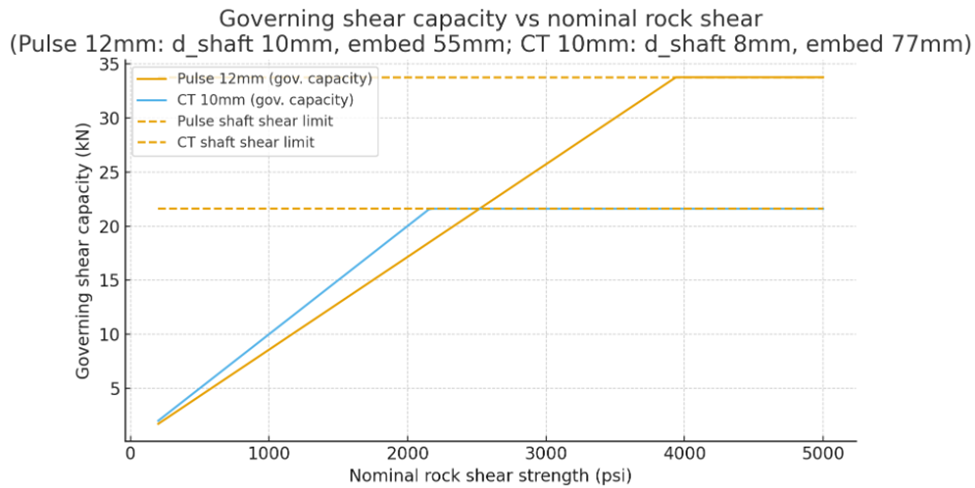
So my conclusion that the CT bolts are better designed for cave rock than the Petzl Pulses is not sensitive to assumptions about Rock-punching reduction factor or the relationship between 2205’s ultimate tensile and ultimate shear strength. The CT bolts come out looking like a better design for cave rock (and, of course, neither was designed for use in caves).
It’s also worth noting that the longer 10mm CT bolt removes 10 percent less rock than the shorter 12mm Petzl bolt. So you’re getting about 10% more bolting per battery.
Returning to axial strength. Because the core principle at work in these bolts is lateral expansion under confinement (a radial pressure multiplier from a low-angle taper), we need to control the hole diameter to achieve the needed confinement. These Climbing Taiwan bolts allow you to torque them down – in a sense. This isn’t torquing to achieve tensile preload, as in wedge anchors. It is about mechanically setting the wedge to the local bore diameter. Think of it like calibrating the anchor to the hole. You can expand the sleeve using the handle until you feel firm engagement. That lets you tune for real-world variability in hole diameter, rock roughness, or small flares and cracks. That seems to me the big advantage of this design; it’s more tolerant of the wobbly drilling that sub-optimal cave settings often give us.
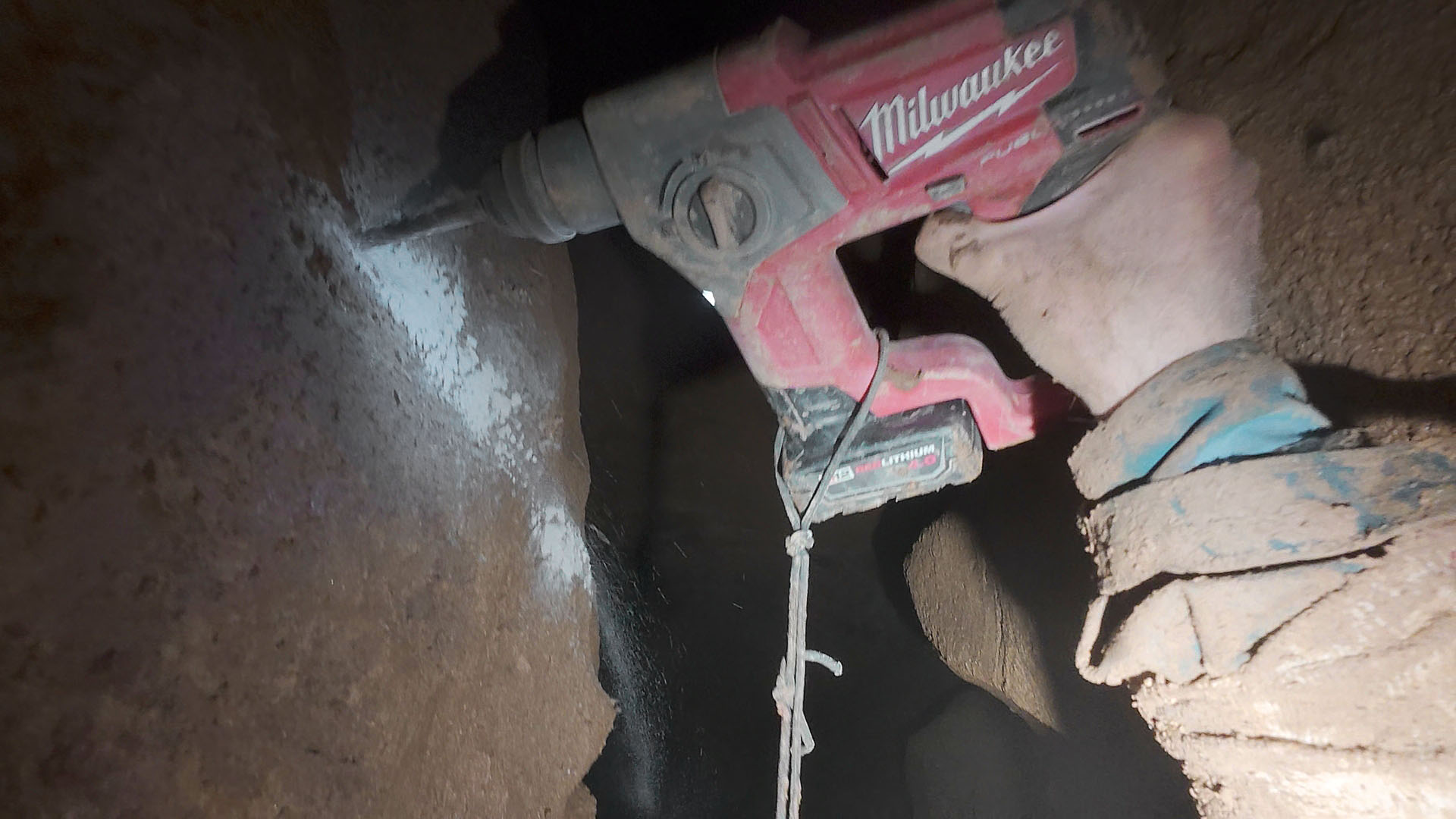
Beyond being easier to clean and having superior strength in soft rock compared to the 12mm Petzl Pulse, the cleverness here is in better decoupling hole-fit adjustment from load resistance. I was able to engage the nominally 10mm bolt in a 12mm diameter hole. I’ll still avoid drilling bad holes, but this is very good to know, especially when drilling in confined or awkward places where suddenly the little Milwaukee decides to go on a rotary rampage.
If you have experience with these underground, or have questions or comments, please feel free to add a comment below. Sometimes I miss real engineering.
Six Days to Failure? A Case Study in Cave Bolt Fatigue
Posted by Bill Storage in Engineering & Applied Physics on July 17, 2025
The terms fatigue failure and stress-corrosion cracking get tossed around in climbing and caving circles, often in ways that would make an engineer or metallurgist cringe. This is an investigation of a bolt failure in a cave that really was fatigue.
In October, we built a sort of gate to keep large stream debris from jamming the entrance to West Virginia’s Chestnut Ridge Cave. After placing 35 bolts – 3/8 by 3.5-inch, 304 stainless – we ran out. We then placed ten Confast zinc-plated mild steel wedge anchors of the same size. All nuts were torqued to between 20 and 30 foot-pounds.
The gate itself consisted of vertical chains from floor to ceiling, with several horizontal strands. Three layers of 4×4-inch goat panel were mounted upstream of the chains and secured using a mix of 304 stainless quick links and 316 stainless carabiners.
No one visited the entrance from November to July. When I returned in early July and peeled back layers of matted leaves, it was clear the gate had failed. One of the non-stainless bolts had fractured. Another had pulled out about half an inch and was bent nearly 20 degrees. Two other nuts had loosened and were missing. At least four quick links had opened enough to release chain or goat panel rods. Even pairs of carabiners with opposed gates had both opened, freeing whatever they’d been holding.
I recovered the hanger-end of the broken bolt and was surprised to see a fracture surface nearly perpendicular to the bolt’s axis, clearly not a shear break. The plane was flat and relatively smooth, with no sign of necking or the cup-and-cone profile typical of ductile tensile failure. Under magnification, the surface showed slight bumpiness, indicating the smoothness didn’t come from rubbing against the embedded remnant of the bolt. These features rule out a classic shear failure from preload loss (e.g., a nut loosening from vibration) and also rule out simple tensile overload and ductile fracture.
That leaves two possibilities: brittle tensile fracture or fatigue failure under higher-than-expected cyclic tensile load. Brittle fracture seems highly unlikely. Two potential causes exist. One is hydrogen embrittlement, but that’s rare in the low-strength carbon steel used in these bolts. The zinc-plating process likely involved acid cleaning and electroplating, which can introduce hydrogen. But this type of mild steel (probably Grade 2) is far too soft to trap it. Only if the bolt had been severely cold-worked or improperly baked post-plating would embrittlement be plausible.
The second possibility is a gross manufacturing defect or overhardening. That also seems improbable. Confast is a reputable supplier producing these bolts in massive quantities. The manufacturing process is simple, and I found no recall notices or defect reports. Hardness tests on the broken bolt (HRB ~90) confirm proper manufacturing and further suggest embrittlement wasn’t a factor.
While the available hydraulic energy at the cave entrance would seem to be low, and the 8-month time to failure is short, tensile fatigue originating at a corrosion pit emerges as the only remaining option. Its viability is supported by the partially pulled-out and bent bolt, which was placed about a foot away.
The broken bolt remained flush with the hanger, and the fracture lies roughly one hanger thickness from the nut. While the nut hadn’t backed off significantly, it had loosened enough to lose all preload. This left the bolt vulnerable to cyclic tensile loading from the attached chain vibrating in flowing water and from impacts by logs or boulders.
A fatigue crack could have initiated at a corrosion pit. Classic stress-corrosion cracking is rare in low-strength steel, but zinc-plated bolts under tension in corrosive environments sometimes behave unpredictably. The stream entering the cave has a summer pH of 4.6 to 5.0, but during winter, acidic conditions likely intensified, driven by leaf litter decay and the oxidation of pyrites in upstream Mauch Chunk shales after last year’s drought. The bolt’s initial preload would have imposed tensile stresses at 60–80% of yield strength. In that environment, stress-corrosion cracking is at least plausible.
More likely, though, preload was lost early due to vibration, and corrosion initiated a pit where the zinc plating had failed. The crack appears to have originated at the thread root (bottom right in above photo) and propagated across about two-thirds of the cross-section before sudden fracture occurred at the remaining ligament (top left).
The tensile stress area for 3/8 x 16 bolt would be 0.0775 square inches. If 65% was removed by fatigue, the remaining area would be 0.0271 sq. in. Assuming the final overload occurred at a tensile stress of around 60 ksi (SAE J429 Grade 2 bolts), then the final rupture would have required a tensile load of about 1600 pounds, a plausible value for a single jolt from a moving log or sudden boulder impact, especially given the force multiplier effect of the gate geometry, discussed below.
In mild steel, fatigue cracks can propagate under stress ranges as low as 10 to 30 percent of ultimate tensile strength, given a high enough number of cycles. Based on published S–N curves for similar material, we can sketch a basic relationship between stress amplitude and cycles to failure in an idealized steel rod (see columns 1 and 2 below).
Real-world conditions, of course, require adjustments. Threaded regions act as stress risers. Standard references assign a stress concentration factor (Kₜ) of about 3 to 4 for threads, which effectively lowers the endurance limit by roughly 40 percent. That brings the endurance limit down to around 7.5 ksi.
Surface defects from zinc plating and additional concentration at corrosion pits likely reduce it by another 10 percent. Adjusted stress levels for each cycle range are shown in column 3.
Does this match what we saw at the cave gate? If we assume the chain and fencing vibrated at around 2 Hz during periods of strong flow – a reasonable estimate based on turbulence – we get about 172,000 cycles per day. Just six days of sustained high flow would yield over a million cycles, corresponding to a stress amplitude of roughly 7 ksi based on adjusted fatigue data.
Given the bolt’s original cross-sectional area of 0.0775 in², a 7 ksi stress would require a cyclic tensile load of about 540 pounds.
| Cycles to Failure | Stress amplitude (ksi) | Adjusted Stress |
| ~10³ | 40 ksi | 30 ksi |
| ~10⁴ | 30 ksi | 20 ksi |
| ~10⁵ | 20 ksi | 12 ksi |
| ~10⁶ | 15 ksi | 7 ksi |
| Endurance limit | 12 ksi | 5 ksi |
Could our gate setup impose 540-pound axial loads on ceiling bolts? Easily – and the geometry shows how. In load-bearing systems like the so-called “death triangle,” force multiplication depends on the angle between anchor points. This isn’t magic. It’s just static equilibrium: if an object is at rest, the vector sum of forces acting on it in every direction must be zero (as derived from Newton’s first two laws of mechanics).
In our case, if the chain between two vertically aligned bolts sags at a 20-degree angle, the axial force on each bolt is multiplied by about a factor of eight. That means a horizontal force of just 70 pounds – say, from a bouncing log – can produce an axial load (vertical load on the bolt) of 540 pounds.
Under the conditions described above, six days of such cycling would be enough to trigger fatigue failure at one million cycles. If a 100-pound force was applied instead, the number of cycles to failure would drop to around 100,000.
The result was genuinely surprising. I knew the principles, but I hadn’t expected fatigue at such low stress levels and with so few cycles. Yet the evidence is clear. The nearby bolt that pulled partly out likely saw axial loads of over 1,100 pounds, enough to cause failure in just tens of thousands of cycles had the broken bolt been in its place. The final fracture area on the failed bolt suggests a sudden tensile load of around 1,600 pounds. These numbers confirm that the gate was experiencing higher axial forces on bolts than we’d anticipated.
The root cause was likely a corrosion pit, inevitable in this setting, and something stainless bolts (304 or 316) would have prevented, though stainless wouldn’t have stopped pullout. Loctite might help quick links resist opening under impact and vibration, though that’s unproven in this context. Chains, while easy to rig, amplified axial loads due to their geometry and flexibility. Stainless cable might vibrate less in water. Unfortunately, surface conditions at the entrance make a rigid or welded gate impractical. Stronger bolts – ½ or even ⅝ inch – torqued to 55 to 85 foot-pounds may be the only realistic improvement, though installation will be a challenge in that setting.
More broadly, this case illustrates how quickly nature punishes the use of non-stainless anchors underground.
Concrete Screws in Cave Exploration
Posted by Bill Storage in Engineering & Applied Physics on June 18, 2025
This hastily assembled piece expresses concerns over the use of concrete screws in caving. It stems from a discussion with Max Elfelt last night. Two aspects of screw use underground interact adversely: 1) screws rely on rock tensile strength while wedge bolts rely on compressive strength, and 2) the uncharacteristically large difference between tensile and compressive strength in cave-forming limestone, particularly oolitic types. Combined, they raise significant concerns. Comments are welcome, either below or privately. Find me in the NSS directory, on X, or LinkedIn.
Cave exploration demands absolute trust in permanent rigging for pits, climbs, and traverses where falls could be fatal. Anchors, the critical connection points securing ropes to cave walls, must withstand the forces of climbers, falls, and environmental wear. While concrete screws have gained attention in some climbing communities for their ease of installation, their use as permanent or semi-permanent rigging in caves and in any cases where axial loads (pullout forces along the anchor’s axis) are possible may pose unacceptable risks.
Unlike wedge bolts, which rely on the rock’s compressive strength to create a secure grip, concrete screws depend heavily on the rock’s tensile and shear strength, properties that appear, on the basis of reported mechanical properties, to be inadequate for safe use of screws in cave-forming limestones, particularly oolitic and anisotropic varieties (those having different properties in different directions, typically caused by depositional discontinuities – bedding planes – or cemented planar fractures). A quick look at the mechanical differences between these materials reveals grounds for concern – possibly grave concern.
The Mechanics of Anchors: Wedge Bolts vs. Concrete Screws
Wedge bolts work by inserting a bolt into a drilled hole, then tightening it (torquing the nut) to push a cone-shaped wedge against the sides of the drilled hole. This action generates a high clamping force called preload. Preload allows the bolt to resist axial loads without any further movement of the bolt in the hole when even large loads are applied to the hanger. The preload is verifiable during installation: if torque is felt by hand or measured with a wrench (27 Nm or 20 foot pounds for 10 mm or 3/8 inch anchors), the rock is compressing adequately, the needed friction has been generated, and the desired preload exists. The physics and mechanics of wedge bolts ensures that applied axial or perpendicular loads, if they are less than the amount of axial preload (several thousand pounds, or greater than 10KN), do not alter the stress states of the installed bolt or the adjacent rock at all. The mechanics of wedge bolts and how they are misunderstood by climbers appears in a paper by Amy Skowronski and me in the Oct 2024 Journal of Search and Rescue.
Concrete screws, in contrast, operate somewhat like screws in wood. However, this analogy has serious limitations, discussed below. Concrete screws are threaded directly into a pre-drilled hole, cutting or crushing threads into the rock. Unlike wedge bolts, preload is not a significant factor of the gripping mechanics. Their resistance to axial loads depends on the mechanical interlock between threads and rock. When a caver applies force – either axial or perpendicular loading – the threads bear against the rock, inducing shear stress as threads resist sliding. Applied axial loads, if present, induce tensile stress as the rock resists radial pulling apart. This makes the rock’s tensile and shear strengths critical, as failure at the thread-rock interface will result in pullout. Cyclic loading – each time a load is added and removed during descending, ascending, or falling – causes wear, micro-fractures, and grain dislodgement. This increases the induced stresses by reducing the size of the surfaces under shear and tensile stress. Use of concrete screws in climbing is discussed in The Bolting Bible, about which I express several concerns below.
Material Mechanical Properties: Concrete vs. Limestone
The suitability of bolts and screw anchors hinges critically on the rock’s mechanical properties. The limestone that forms most caves has highly variable strength, unlike concrete, which is engineered for consistency. More critically, the relationship between compressive strength and tensile strength is predictable in concrete, but less so in limestone. Below are comparisons of compressive and tensile strengths, focusing on cave-relevant limestones, particularly oolitic and anisotropic types.
| Property | Structural Concrete | Oolitic Limestone | Anisotropic Limestone |
|---|
| Compressive Strength | 20–200 MPa | 20–60 MPa (varies with porosity and cementation) | ~20–180 MPa (depending on bedding and orientation) |
| Tensile Strength (Direct) | 2–5 MPa | ~0.5–4 MPa | Highly variable: ~0.5–6 MPa depending on bedding details |
| Modulus of Rupture | 3–7 MPa | ~0.5–5 MPa | ~0.5–12 MPa |
| Anisotropy | Highly isotropic | Weakly anisotropic | Strongly anisotropic (bedding planes matter greatly) |
| Failure Mode in Tension | Brittle fracture | Grain-boundary separation | Splitting along bedding or delamination |
| Elastic Modulus (Young’s) | 25–50 GPa (typical NSC) | ~5–30 GPa | ~10–50 GPa, highly dependent on direction |
* Granite, for comparison, often has a compressive strength of 100–200 MPa and a tensile strength of ~7–20 MPa. Tensile strength measurements are from splitting (ASTM C496) and flexure (ASTM C78) tests. Low-tensile oolite strength values from Ippolito (1975), Szechy (1966), and Paronuzzi (2009).
Why Concrete Screws in Caves Might Be Riskier than We Think
The disparity between compressive and tensile strengths in limestone, particularly oolitic and anisotropic types, is large. Wedge bolts rely on limestone’s compressive strength (20 MPa or greater), which is sufficient to develop preload in typical cave limestones. The preload reduces reliance on the rock’s tensile/shear strength and eliminates cyclic wear concerns for expected loads.
Concrete screws depend on limestone’s tensile and shear strength, not its compressive strength) to resist axial loads. Stresses induced by cavers’ weight or falls (e.g., 5–15 kN, translating to 1–3 MPa at the thread interface, depending on thread geometry – see sample calculations at the bottom of this post) are dangerously close to (and possibly exceed in cases) the tensile strengths of the limestone in which they are placed. In some oolitic limestone, the weak matrix fails under thread stresses, causing grain dislodgement or micro-fractures, especially under cyclic loading, though specific performance data in cyclic loading in material like oolitic limestone is lacking. Unlike wedge bolts, where preload is confirmed at installation, concrete screws offer no such assurance, and their performance necessarily degrades over time because each each load application results in fretting fatigue. Common caving field-tests for limestone compressive strength (e.g., the ring of a hammer blow) are unlikely to reliably predict tensile strength, particularly when the tensile strength of the matrix is low compared to that of the grains (clasts), as is the case with many oolitic limestones.
This disparity arises because both hard and soft rocks can undergo brittle fracture and are prone to tensile failure under localized stresses, whereas they resist compression better, due to grain-to-grain contact even after the matrix yields. In oolitic limestone, the rock consists of hard, spherical grains (ooids) cemented by a softer matrix (e.g., calcite). The matrix’s tensile and shear strengths are significantly lower than the bulk compressive strength, which is dominated by the hard grains. When a concrete screw is installed, its threads cut or crush into the matrix, and under axial load, the matrix must resist shearing or tensile failure. If the matrix is weak (e.g., porous or amorphous cement), the threads can dislodge grains by fracturing the matrix, reducing pullout strength over time, especially under cyclic loading. Manufacturers like Simpson Strong-Tie (Titen HD screws) report pullout strengths of 42–52 kN in hard limestone and concrete, but these assume isotropic substrates, not cave limestones with weak matrices or bedding planes.
Another consideration gives rise to even greater concern regarding placement in oolitic limestones, particularly those with large ooids. ASTM C496 tensile strength tests seem likely to overestimate oolitic limestone’s tensile strength for predicting concrete screw pullout. Overestimation of tensile strength for the screw scenario is likely because of the large size of the test specimen (152 mm, 6 inches), the test’s bulk measurement (e.g., 2–5 MPa) versus the matrix’s lower tensile/shear strength (e.g., 1–3 MPa) and the size of ooids compared to that of the threads (1–2 mm threads and .25–1 mm ooids). The test’s homogenized results probably don’t capture localized matrix failure adjacent to threads.
Cause for Concern in the Common Caving Use Case
Our discussions with cavers who use concrete screws suggest that they are used only for aid climbs (temporary placement) and only where the nominal applied load is not axial, i.e., they use horizontal screws with vertical applied loads. This, in theory, would eliminate concerns about the low tensile strength of certain limestones. One part of the allure of concrete screws is that no hammer or wrench is needed for installation. If hammer, wrench, and wedge anchors aren’t available at the top of a climb, screws then take on a role slightly more critical than their use on the climb itself. Many scenarios at the top of climbs entail a descent setup where some degree of axial loading is inevitable. All descents entail some degree of cyclic loading. Similarly, a fall when the climber is above a single bolt (first bolt placed only) in a climb will always result in significant axial loading.
Five factors combine to raise considerable concern for these and similar scenarios.
- The unusual relationship between compressive and tensile strength of common limestones.
- The absence of evidence for how many load cycles are needed to cause significant tensile yielding of the internal threads carved by screws
- The small margin between tensile strength (ultimate tensile stress) of certain limestones and normal working loads in use
- The lack of confirmation of a successful screw installation such as the resistance to torquing with wedge bolts
- Inability to assess tensile strength of the limestone by a means such as listening to the sound of a hammer blow
Intuitions about strength properties of common materials may further exacerbate the situation. Metals’ tensile strength is typically 80 or 90 percent of its compressive strength. In limestone, this ratio is 10 to 15%. In oolitic and anisotropic limestone, it can be below 5 percent.
Finally, the prominence of analyses of climbing gear – gear used on the surface – consisting mainly of dramatic measurement of ultimate strength may work against us. Pull-tests, while entertaining, are not particularly useful in evaluating the utility of any mechanical component. Cavers may face increased risk by extending conclusions drawn from non-representative test scenarios common on YouTube, for example.
This concludes the thrust of my concern about concrete screws in caves. I welcome comments and corrections. Below are sections on calculating expected pullout loads of screws, discussion of fatigue and fretting fatigue, and specific concerns on the discussion of concrete screws in the Bolting Bible. These are engineering/physics oriented, and the above concerns hold independent of the topics below. Stop here if you’re not drawn math, physics, or nit picking.
The Bolting Bible
The Bolting Bible offers much useful instruction and information on bolts and screws used in climbing. The article/chapter “The Book of Concrete Screws” by HowNOT2 aims to educate climbers about concrete screws as temporary or sometimes permanent anchors in rock climbing. While it provides practical insights and test data, it has, in my opinion, several shortcomings in terms of physics and engineering rigor. That rigor seems to me something that should be present in coverage of a relatively new technique, especially when any discussion of permanent rigging is present. The Bolting Bible explicitly disclaims scientific rigor but its comprehensiveness is understood by many to imply authority.
The article describes concrete screws as functioning “similarly to normal wood screws” where “threads bite into the sides of the hole.” The analogy may aid visual intuition, but it risks conflating fundamentally different material behaviors – elastic-plastic deformation in wood versus brittle fracture and micro-spalling in rock. It fails to explain how the threads interact with the rock substrate, particularly the stress concentrations at the thread-rock interface.
The article mentions that concrete screws are “not safe in soft rock” and can “strip the threads” in hard rock, but it provides no quantitative or mechanical reasoning. Hard and soft don’t adequately cover the variations in mechanical properties of rock to orient readers toward meaningful distinctions in substrate performance.
The article briefly notes that cyclic loading in soft rock can cause concrete screws to “lose grip” due to threads dislodging material. “Losing grip” is a casual phrase that erases the actual failure modes involved: local pulverization of rock around threads, progressive thread shearing, and fretting fatigue under micro-motion (see discussion of fatigue at bottom). The language reduces complex, cumulative damage to a vague sensation.
The article cites break tests (e.g., Simpson Strong-Tie Titen HD screws achieving 42–52 kN [9400–11700 pounds] before head shear. The head-shear test is meaningless to climbing or caving use cases and might create a false sense of safety margin. While empirical data is valuable, the absence of a theoretical framework (e.g., thread shear strength, rock compressive strength) limits the generalizability of the findings and utility of the conclusions.
The suggestion to “spit or squirt water,” though possibly derived from field experience, should be followed by some observed benefit with even a speculative mechanism: Does moisture reduce dust, increase thread cutting efficiency, or initiate micro-hydration in porous substrates? Without this, it reads as lore rather than low-tech science.
As is the case with most gear analyses that measure ultimate strength, the article’s focus on ultimate strength (e.g., head shear at high loads) misses the more relevant issue for climbers: long-term reliability under repeated sub-failure loads, particularly given the key difference in mechanism between wedge bolts, with which most cavers are familiar, and concrete screws, which have come onto the scene fairly recently.
The article emphasizes ease of installation and removal for temporary anchors but does not adequately address the ethical implications of leaving potentially compromised holes in rock, especially in public climbing areas. Drilling holes is a “permanent deformation to the rock,” as noted elsewhere in The Bolting Bible, yet the article does not discuss how concrete screw holes might affect future bolting. “Bolt-farm” problems of the past might shift to hole-farm problems.
An assoicated HowNot2 video mentions permanent rigging using screws, stating that the screws should be stainless steel. Stainless eliminates the problem of screw deterioration from corrosion. This is a distraction from the more relevant concern of hole degradation. The video mentions that repeated use has led to “spinners” without noting that if a screw spins, the threads it carved into the rock are completely compromised. If a screw spins, unlike the case with a wedge bolt, it has no resistance to pullout.
Expected Pullout Load in Low-Tensile Oolitic Limestone
To calculate the effective contact area of a 3/8-inch diameter, 3-inch long concrete screw in tension, we must estimate the area over which the threads engage the concrete and can transfer tensile load. This is not the same as the root cross-sectional area of the screw (which governs tensile failure of the screw itself); you’re asking about the interface area between the screw threads and the concrete, which governs pullout or bond failure.
Nominal Parameters
- Screw outer diameter: 3/8 inch = 0.375 in
- Length embedded in concrete: 3 inches
(Assuming full 3-inch embedment and no voids) - Thread type: typical concrete screw (e.g., Tapcon) with a coarse thread (approx. 7–8 threads per inch)
Basic Bond Area (Cylindrical Surface)
This is a simplification that treats the bond area as a cylinder with the mean thread diameter:
Total contact area = π ⋅ mean diameter ⋅ embedded length where:
mean diameter = (outer diameter – root diameter) / 2
For a 3/8″ 3-inch Tapcon-style screw:
Outer diameter ≈ 0.375 in.
Root diameter ≈ 0.275 in.
Mean diameter ≈ (0.375 + 0.275)/2 = 0.325 in
Therefore, total contact area ≈ π ⋅ 0.325 ⋅ 3 ≈ 3.06 sqin.
Thread Engagement Area
Threads only contact the concrete at the flank surfaces, not over the full cylindrical shell. Accounting for thread flank angle and spacing typically reduces effective contact area to 40–60% of the full cylindrical surface, depending on thread profile.
Assuming 50% effective contact: Contact area = 1.5 sqin.
Tensile strength of weak but not weakest oolitic limestone = 1MPa = 145 psi. Note that reports on limestone tensile tests indicate that strengths lower than 1MPa could be encountered in oolitic and anisotropic limestones. West Virginia’s Pickaway Limestone comes to mind.
Expected pullout load in limestone having 1MPa (145 psi) tensile strength = 150 psi ⋅ 1.5 sqin = 225 pounds (or 112 pounds for 0.5 MPa tensile limestone)
Fatigue
The term fatigue, as used in engineering, has specific technical meanings that might differ from how it is used casually in discussing gear. The most general use describes gradual reduction in strength after many cycles (typically 10,000 to 1 million cycles) of stress application where the applied stress involves superficially elastic deformation (as opposed to plastic deformation in which measurable yielding of material occurs).
Low cycle fatigue in metals describes strength reduction from cyclic loading up to about 10,000 cycles where measurable plastic (doesn’t bounce back) deformation occurs.
Both high and low-cycle fatigue in metals happen when, at the microscopic level, even when the macroscopic stress is elastic, dislocations move within favorably oriented grains of the crystalline metal. 304 stainless steel typically has an ASTM grain size number of 5 to 10, corresponding to grain diameters of about 15 to 65 microns. Repeated dislocation during cyclic loading can form persistent slip bands, which are localized zones of plastic deformation that can eventually break through the surface. These act as initiation sites for fatigue cracks.
Localized plastic deformation around slip bands creates intrusions and extrusions on the surface. Over thousands to millions of cycles, these become tiny microcracks, usually less than a grain diameter long. Initially, crack growth follows crystallographic planes (especially {111} slip planes in body-centered cubic or face-centered cubic structures – for those who are into crystals). This is called Stage I (shear-mode) propagation.
Once a crack crosses a few grains, it becomes long enough to be governed by stress intensity rather than just local slip. The crack then grows perpendicular to the maximum principal stress (Stage II, or tensile-mode crack growth). When the crack becomes long enough that the remaining material cross-section can’t support the applied load, sudden ductile or brittle fracture occurs, depending on material properties (particularly its toughness) and loading rate.
From this description, you can see that fatigue is unlikely to be a failure mode in either wedge bolts or concrete screws as used in caves or in rock climbing (in contrast to what is stated in climbing literature here and here); the applied loads are too small and the number of cycles is too low.
Above I used the term fretting fatigue to describe rock wear along the threads carved into the rock by a concrete screw. I want to be careful in using a term possibly in a non-standard way. This is a very different use of the general term fatigue in mechanics. Here I refer to a form of fatigue failure that occurs when a component (rock in this case, not the screw) experiences both cyclic loading and simultaneous small-amplitude oscillatory motion (microslip) at the contact surface with another component (the screw). This microscale rubbing involves very high contact forces and greatly reduces component life – to a degree that the term fatigue does not apply like it does in the cyclic loading of metal. Fretting fatigue usually describes a condition found at bolted joints, riveted connections, spline shafts, blade roots, or where two components are clamped but subjected to vibration or relative motion.
