Posts Tagged aid climbing
Cave Bolts – 3/8″ or 8mm? – Or Wrong Question?
Posted by Bill Storage in Engineering & Applied Physics on September 2, 2025
Three eighths inch bolts – or 8mm? You’ll hear this debate as you drift off to sleep at the Old Timers Reunion. Peter Zabrok laughs it off: quarter inch, he says, for climbing. Sure, on El Capitan, where Pete hangs out, quarter inch is justifiable – clean granite, smooth walls, long pitches. But caves – water-carved knife edges, mud, rock of wildly varying strength, and the chance of being skewered on jagged breakdown – give rise to a different calculus of bolt selection.
It’s easy to look up manufacturers’ data and see that 8mm is “super good enough.” The phrase comes from a YouTube channel that teaches– perhaps inadvertently – that ultimate strength is all that matters. I’m cursed with a background in fasteners. I’ve looked at too many failed bolts under scanning electron microscopes. I’ve been an expert witness in cases where bolts took down airplanes and killed people. From that perspective, ultimate breaking strength is a lousy measure of gear. Let’s reframe the 3/8 vs 8mm (M8) diameter question with an engineer’s eye – and then look at bolt length.
The Basics without the Fetish
Let’s keep this down to earth. I’ll mostly use English units – pounds and inches. Most cavers I know can picture 165 pounds but have no feel for a kilonewton. Physics should be relatable, not a fetish. Note: 8mm is close to 5/16 inch (0.314 vs 0.3125), but don’t mix metric drills with imperial bolts.
Stress = force ÷ area. Pull 10 pounds on a one-square-inch rod, you get 10 psi. Pull 100 pounds on ten square inches, you also get 10 psi. This is an example of tensile stress.
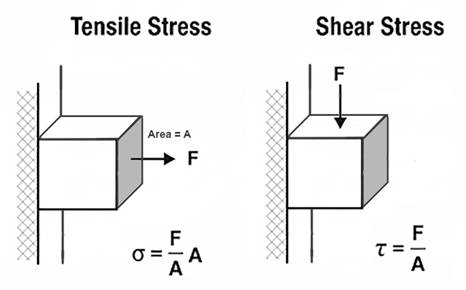
Shear stress is the sideways cousin – one part of a bolt sliding past the other, as when a hanger tries to cut it in half, to cut (shear) the bolt across its cross-section.
Ultimate stress (ultimate strength) is the max before breakage. Yield stress (yield strength) is the point where a bolt stops bouncing back and bends or stretches permanently. For metals, engineers define yield strength as 0.2% permanent deformation. Ratios of yield-to-ultimate vary wildly between alloys, which matters in picking metals. Note here that “strength” refers to an amount in pounds (or newtons) when applied to a part like a bolt but to an amount in pounds per square inch (or pascals) when applied to the material the part is made from.
Bolts in Theory, Bolts in Caves
The strength of wedge anchor made of 304 stainless depends on 304’s ultimate tensile strength (UTS) and the effective stress area of the bolt’s threaded region. Standard numbers: UTS ≈ 515 MPa (75,000 psi). For an M8 coarse bolt, tensile area = 36.6 mm². For a 3/8-16 UNC, it’s 50 mm².
As detailed elsewhere, a properly installed (properly torqued) bolt is not loaded in shear, regardless of the bolt orientation (vertical or horizontal) or the load application direction (any combination of vertical or sideways). But most bolts installed in caves are not properly installed. So we’ll assume that vertical bolts are properly torqued (otherwise they would fall out) and that horizontal bolts are untorqued. In such cases, horizontal bolts are in fact loaded in shear; the hanger bears directly on the bolt.
We can first look at the tension case – a wedge anchor in the ceiling; you hang from it. The axial (tensile) strength is calculated as UTS × A. This formula falls out of the definition of tensile stress: σ = F / A_t, where F is the axial force and A_t is the effective area over which the tensile stress acts. Shear stress (conventionally denoted τ where tensile stress is denoted σ) is defined as τ = F / A_s, where A_s is the area over which the shear stress acts.
In a bolt, A_t and A_s would seem to be identical. In fact, they are slightly different because the shear plane often passes through the threaded section at a slight angle from the tensile plane, thereby reducing the effective area. More importantly, ductile materials like 304 stainless steel undergo plastic deformation at the microscopic scale in a way that renders the basic theoretical formula (τ = F / A_s) less applicable. In this situation, the von Mises yield criterion (aka distortion energy theory) is typically used to predict failure under combined stresses. This criterion relates shear ultimate strength to tensile yield strength. The maximum shear stress a material can withstand (τ_max) is approximately equal to σ_yield / √3 × σ_yield. For predicting ultimate shear strength (USS), theory and empirical test data show that bolts made of ductile metals like mild carbon steel or 304 stainless have ultimate shear strength that is about 0.6 × their ultimate tensile strength.
The tensile stress area (A_s) for an M8 coarse thread bolt is 36.6 mm² (0.057 in²). For a 3/8-16 UNC bolt, A_s is 50 mm² (0.078 in²).
Simple math says:
| Diameter | Tensile Stress Area | Axial Strength | Shear Strength |
| M8 | 36.6 mm² | 4,236 lb | 2,542 lb |
| 3/8 inch | 50 mm² | 5,798 lb | 3,479 lb |
The 3/8 inch bolt has 37% higher tensile and shear strength than the M8 bolt, due to its larger effective cross-section. These values are ultimate strengths of the bolts themselves. Actual load capacities (strengths) of the anchor placement might be lower – if a hanger breaks, if the rock breaks (a cone of rock pulls away), or if the bolt pulls out (the rock yields where the bolt’s collar presses into it).
For reasons cited above (von Mises etc.), the shear strength of each bolt size is less than its tensile strength. For the 8mm bolt, is 2500 pounds (11 kn) strong enough? That’s about a factor of 14 greater than the weight of a 180 pound (80 kg) caver. That’s 14 Gs, which is about the maximum force that humans survive in harnesses designed to prevent a person’s back from bending backward – lumbar hyperextension. Caving harnesses, because of the constraints of single rope technique (SRT), do not supply this sort of back protection. Five to eight Gs is often cited as a likely maximum for survivability in a caving harness.
So 2500 pounds of shear strength seems strong enough, though possibly not super strong enough, whatever that might mean. Is the ratio of bolt strength to working load big enough? The ratio of survivable load to bolt strength? How might a person expecting to experience only the force of his body weight suddenly experience 5Gs?
The UIAA (International Climbing and Mountaineering Federation) sets a maximum allowable impact force for ropes at 12 kN (2700 lb) for a single rope, which means roughly 6-9 Gs for an average climber (75 kg, 165 lb.)
When a bolt is preloaded (tightened to a specified torque, often approaching its yield strength), it induces a compressive force in the clamped materials (the hanger, washer, and the rock) and a tensile stress of equal magnitude in the bolt. For a preloaded bolt, an externally applied load does not increase the tensile stress in the bolt until the external load approaches the preload force. This is because the external load first reduces the compressive force in the clamped materials rather than adding to the bolt’s tension. This behavior is well-documented in bolted joint mechanics (e.g., Shigley’s Mechanical Engineering Design).
For loads perpendicular to the bolt axis, preload can significantly enhance the bolted joint’s shear capacity. The improvement comes from the frictional resistance generated between the clamped surfaces (e.g., the hanger and concrete) due to the preload-induced compressive force. This friction can resist shear loads before the bolt itself is subjected to shear stress.
Basing preload on the yield strength of the bolts’ 304 stainless material (215 MPa, 31,200 psi) and the cross-sectional area of the threads used above gives the following preload forces:
M8 bolt preload: 215 MPa × 36.6 mm² ≈ 7,869 N (1,767 lb).
3/8 inch bolt preload: 215 MPa × 50 mm² ≈ 10,750 N (2,413 lb).
If we assume a coefficient of friction of 0.4 between hanger and bedrock, we can calculate the frictional forces perpendicular to horizontally placed bolts. These frictional forces can fully resist perpendicular (vertical) loads up to a limit of μ × preload (where μ is the friction coefficient and F_friction = μ × F_preload). For μ = 0.4, the shear resistance from friction alone could be:
M8: 0.4 × 7,869 N ≈ 3,148 N (707 lb).
3/8 inch: 0.4 × 10,750 N ≈ 4,300 N (966 lb).
These frictional capacities are substantial, meaning the bolt’s shear strength becomes relevant only if the frictional capacity is exceeded. The preload is highly desirable, because it prevents the rock and the bolt from “feeling” the applied load, and therefore prevents any cyclic loading of the bolt, even when cyclic loads are applied to the joint (via the hanger).
However, the frictional capacity (707 lb for M8) usually does not add to the shear capacity of the bolt, once preload is exceeded. Its shear capacity remains at 2542 lb as calculated above, because once the hanger slips relative to the rock, the bolt itself begins to bear the shear load directly.
Now, with properly torqued, preloaded bolts, we can return to the main question: are M8 bolts “good enough”? Two categories of usage come to mind – aid climbing and permanent rigging. Let’s examine each, being slightly conservative. For example, we’ll assume no traction or embedding of the hanger, something that often but not always exists, which results in an effective coefficient of friction between rock and hanger of 1.0 or more. We’ll use 8Gs as a threshold of survivability and 0.4 as a coefficient of friction – though friction becomes mostly irrelevant in this worst-case analysis.
Comparative Analysis – 3/8 vs M8 (first order approximations)
For an M8 bolt, preload near yield (215 MPa × 36.6 mm² = 7.9 kN / 1,767 lb) gives a frictional capacity of 0.4 × 7.9 kN = 3.16 kN (707 lb).
For a 3/8 inch bolt (215 MPa × 50 mm² = 10.8 kN / 2,413 lb), it’s 0.4 × 10.8 kN = 4.3 kN (966 lb).
The 8 G threshold (80 kg climber, 8 × 785 N = 6.3 kN / 1,412 lb) exceeds both frictional capacities, meaning the joint slips, and the bolt bears shear stress in these high-load cases, regardless of torquing.
Once friction is exceeded, the bolt’s shear strength governs: 11.3 kN (2,542 lb) for 8mm, 15.5 kN (3,479 lb) for 3/8 inch (based on 0.6 × UTS = 309 MPa).
Both M8 and 3/8 exceed 6.3 kN, confirming that the analysis hinges on shear strength, not friction, for high-load cases. Torquing is critical to achieve the assumed preload (near yield) and to confirm placement quality (a torqued bolt indicates a successful installation). However, in high-load cases (≥6.3 kN), the frictional capacity is irrelevant once exceeded, and the analysis stands on the bolt’s shear strength and the rock integrity.
Since high-load cases (e.g., 8 G = 6.3 kN) exceed the frictional capacity of both bolt diameters (3.16 kN for 8mm, 4.3 kN for 3/8 inch), the decision rests on shear strength margin:
M8: 11.3 kN (2,542 lb) provides a ~1.8x factor of safety (see note at bottom on factors of safety) over 6.3 kN.
3/8 inch: 15.5 kN (3,479 lb) offers a ~2.5x factor, ~37% higher, giving more buffer against rock variability or slight overloads.
In some limestone (10–100 MPa), the rock will fail (e.g., pullout) well below the bolt’s shear strength. Remember that with torqued bolts the rock does not “feel” any load until the axial load exceeds preload or the perpendicular load exceeds the friction force generated by the preload. But in softer (low compressive strength) limestone, once those thresholds are exceeded, the rock often fails before the bolt fails in shear or tension. 3/8 inch’s larger diameter distributes load better, reducing rock stress (bearing stress = force / diameter × embedment).
Most of us use redundant anchors for permanent rigging, and you should too. A dual-anchor system with partial equalization (double figure eight, bunny-loop-knot, 1–3 inch drop limit) ensures no single failure is catastrophic. A 3-inch drop would add ~1 kN to the force felt by the surviving anchor. This is within the backup bolt’s shear capacity, making 8mm viable.
What about practical factors? M8 bolts save ~20–35% battery life and weight, critical for remote locations. M8 does not align with ASC/UIAA standards (≥3/8 inch preferred). 3/8 is obviously better for permanent anchors in marginal rock, not because the bolt is stronger, but because the contact stresses are about 35% lower – a potentially significant difference.
Effect of Bolt Length on Anchor Failure in Limestone
In typical installations of wedge bolts in limestone, axial (tensile) loading, steel failure often governs (e.g., the bolt fractures at the threads), while in shear loading, the anchor typically experiences partial pullout with bending, followed by a cone-shaped rock breakout (pry-out failure). This is consistent with industrial experience in concrete, where tensile failures are steel-dominated due to the anchor’s expansion mechanism providing sufficient grip, but shear failures involve pry-out because the load induces bending and leverages the embedment. The collar (sleeve, expansion clip) in most brands is identical for all bolt lengths of a given diameter. The gripping mechanism doesn’t change with length. The primary difference is the effective embedment depth (h_ef), which affects load distribution in the rock. Longer bolts increase the volume of rock engaged and better resistance to breakout, but this benefit is more pronounced in shear than tension, as preload clamping compresses a larger rock section under the hanger, distributing stresses and reducing localized crushing.
To estimate failure loads for 2.5 inch vs. 3.5 inch total lengths, we can use standard engineering formulas adapted from ACI 318* (* I won’t violate copyright by linking to outlaw PDFs, but I think standards bodies that sell specs for hundreds of dollars do the world a huge injustice) for post-installed wedge anchors, treating limestone as analogous to concrete, with adjustments for its variable strength.
The compressive strength of limestone (f_c’) varies from 1,000 psi (soft, e.g., oolitic limestone) to 10,000 psi (harder types). We’ll use 4,000 psi (27.6 MPa) based on typical Appalachian limestone values. For stronger (compressive strength) limestone (e.g., 8,000 psi / 55 MPa), capacities increase by1.4x (proportional to the square root of f_c’).
Embedment Depth (h_ef) is the bolt length minus hanger thickness (~0.25 inch) and nut/washer (~0.375 inch). Thus, h_ef ≈ 1.875 inches for 2.5 inch bolt; h_ef ≈ 2.875 inches for 3.5 inch bolt. This assumes that a “good” hole has been drilled, allowing the collar to catch immediately as the bolt is torqued.
We’ll assume 304 stainless, ultimate tensile ~5,798 lb (25.8 kN), ultimate shear ~3,479 lb (15.5 kN), as previously calculated. 316 alloy would give similar results. We’ll assume proper torquing for preload and no edge effects, meaning the bolt is at least 10 bolt-diameters from edges and cracks.
Formulas (ACI-based, ultimate loads):
- Tensile Rock Breakout: N_cb ≈ 17 × √f_c’ × h_ef^{1.5} lb (k_c=17 for post-installed in cracked conditions; use for conservatism; f_c’ in psi, h_ef in inches).
- Axial Failure Load: Min(N_cb, steel tensile).
- Shear Pry-Out: V_cp ≈ k_cp × N_cb (k_cp=1 for h_ef < 2.5 inches; k_cp=2 for h_ef ≥ 2.5 inches, reflecting increased resistance to rotation).
- Shear Failure Load: Min(V_cp, steel shear), but with bending preceding rock failure.
- Capacities are ultimate (failure); apply safety factors (e.g., 4:1 per UIAA) for working loads.
With these formulas we can compare different bolt lengths in axial loading. Longer bolts increase h_ef, enlarging the breakout cone and distributing tensile stresses over greater rock volume. Preload clamping compresses the rock under the hanger (area ~0.5-1 in² depending on washer diameter), and longer bolts may slightly reduce localized stress concentrations at the surface due to better load transfer deeper in the hole. If rock breakout capacity exceeds steel strength, the bolt fractures. In weaker limestone, rock governs; in harder, steel does. The identical sleeve means expansion grip is consistent, so length primarily affects rock engagement.
So for 4000 psi limestone and 3/8 bolts in tension, axially loaded, we get:
2.5 inch (h_ef ≈ 1.875 in): N_cb ≈ 17 × 63.25 × (1.875)^{1.5} ≈ 2,765 lb (12.3 kN). Rock breakout governs (cone failure).
3.5 inch (h_ef ≈ 2.875 in): N_cb ≈ 17 × 63.25 × (2.875)^{1.5} ≈ 5,240 lb (23.3 kN). Rock breakout governs (cone-pullout).
For M8 bolts, axially loaded (2.5 in. ≈ 64mm, 3.5 in ≈ 90mm):
2.5 inch (h_ef ≈ 1.875 in): N_cb ≈ 17 × √4,000 × (1.875)^{1.5} ≈ 17 × 63.25 × 2.576 ≈ 2,765 lb (12.3 kN). Steel tensile = 4,236 lb (18.8 kN). Rock breakout governs (cone failure).
3.5 inch (h_ef ≈ 2.875 in): N_cb ≈ 17 × 63.25 × (2.875)^{1.5} ≈ 17 × 63.25 × 4.873 ≈ 5,240 lb (23.3 kN). Steel tensile = 4,236 lb (18.8 kN). Steel fracture governs (bolt breaks at threads, matching test observations).
2,765 lb (for both 3/8 and M8 bolts), particularly in redundant anchors, seems reasonable, based on the limits of human survivability and on the other gear in the chain. Nevertheless, this result surprised me. One-inch greater length doubles the effective anchor strength for axial loads.
When a shear load is large enough to exceed bolt preload (which should never happen with actual working loads), the shear force induces bending (lever arm from hanger to expansion point) and pry-out, where the bolt rotates, pulling out the back side and causing a cone breakout. Longer bolts increase h_ef, enhancing pry-out resistance by engaging more rock mass and distributing compressive stresses. If pry-out exceeds steel shear capacity, the bolt bends and shears. Industrial studies show embedment beyond 10x diameter (3.75 inches for 3/8 inch, 80mm for M8 bolts) adds minimal shear benefit.
For 4,000 psi limestone and 3/8 bolts with tensile loads:
2.5 inch (h_ef ≈ 1.875 in < 2.5 in): V_cp ≈ 1 × 2,765 lb ≈ 2,765 lb (12.3 kN). Rock pry-out governs (partial pullout, bending, then cone breakout).
3.5 inch (h_ef ≈ 2.875 in > 2.5 in): V_cp ≈ 2 × 5,240 lb ≈ 10,480 lb (46.6 kN) > steel shear → Steel governs (~3,479 lb [15.5 kN], with bending preceding shear failure).
For stronger limestone (8,000 psi compressive), 3/8 bolt capacities are ~1.4x higher (e.g., 3,870 lb for 2.5 in pry-out; steel 3,479 lb for 3.5 in), emphasizing length’s role in shifting from rock to steel failure.
For 4,000 psi limestone and M8 bolts with shear loads:
2.5 inch (h_ef ≈ 1.875 in < 2.5 in): V_cp ≈ 1 × 2,765 lb ≈ 2,765 lb (12.3 kN). Steel shear = 2,542 lb (11.3 kN). Steel shear governs (barely – bolt bends, then shears, with partial pullout).
3.5 inch (h_ef ≈ 2.875 in > 2.5 in): V_cp ≈ 2 × 5,240 lb ≈ 10,480 lb (46.6 kN). Steel shear = 2,542 lb (11.3 kN). Steel shear governs (bolt bends/shears before rock pry-out).
For harder limestone (8,000 psi), M8/8 bolt capacities are ~1.4x higher, again emphasizing length’s role in shifting from rock to steel failure.
2.5 inch: V_cp ≈ 1 × 3,870 lb ≈ 3,870 lb (17.2 kN). Steel = 2,542 lb. Steel shear governs.
3.5 inch: V_cp ≈ 2 × 7,340 lb ≈ 14,680 lb (65.3 kN). Steel = 2,542 lb. Steel shear governs.
Summary – Failure Loads in 1,000, 4,000, and 8,000 psi Limestone
([S] indicates steel failure, [R] indicates rock failure. Loads given in pounds and (kilonewtons):
| Bolt Size | 2.5 in Axial | 2.5 in Shear | 3.5 in Axial | 3.5 in Shear |
| 1000 psi limestone | ||||
| M8 (8mm) | 1,382 (6.15) [R] | 1,382 (6.15) [R] | 2,620 (11.7) [R] | 2,542 (11.3) [S] |
| 3/8 inch | 1,382 (6.15) [R] | 1,382 (6.15) [R] | 2,620 (11.7) [R] | 2,620 (11.7) [R] |
| 4000 psi limestone | ||||
| M8 (8mm) | 2,765 (12.3) [R] | 2,542 (11.3) [S] | 4,236 (18.8) [S] | 2,542 (11.3) [S] |
| 3/8 inch | 2,765 (12.3) [R] | 2,765 (12.3) [R] | 5,240 (23.3) [R] | 3,479 (15.5) [S] |
| 8000 psi limestone | ||||
| M8 (8mm) | 3,870 (17.2) [R] | 2,542 (11.3) [S] | 4,236 (18.8) [S] | 2,542 (11.3) [S] |
| 3/8 inch | 3,870 (17.2) [R] | 3,870 (17.2) [R] | 5,798 (25.8) [S] | 3,479 (15.5) [S] |
Bottom Line
For me, the key insight is that shear pry-out capacity in limestone anchors scales significantly with embedment depth. Extending bolt length from 2.5 to 3.5 inches increases pry-out resistance by approximately 100–200%, driven by the deeper rock engagement and the ACI 318 k_cp factor (1 for h_ef < 2.5 inches, 2 for h_ef ≥ 2.5 inches), though it’s ultimately capped by the bolt’s steel shear strength (2,542 lb / 11.3 kN for 8mm, 3,479 lb / 15.5 kN for 3/8 inch). When rock strength governs failure, as it often does in weaker (compressive strength) limestone (e.g., 1,000–4,000 psi), 3/8 inch bolts offer no advantage over 8mm (M8), as both have identical rock-limited capacities (e.g., 1,382 lb in 1,000 psi, 2,765 lb in 4,000 psi at 2.5 inches). Thus, choosing a 3.5 inch bolt over a 2.5 inch bolt is typically more critical than choosing between 3/8 inch and 8mm diameters.
Most bolts, particularly wall anchors in aid climbing or permanent setups, experience perpendicular loads. These are initially resisted by friction from tensile preload (e.g., 707 lb for 8mm, 966 lb for 3/8 inch with μ = 0.4), but when loads exceed this – as in a severe 8 G fall (1,412 lb / 6.3 kN for an 80 kg climber) – shear stress initiates. In caves I visit, permanent anchors are redundant, using dual bolts with crude equalization to limit drops to 1–3 inches, ensuring no single failure is catastrophic. In aid climbing, dynamic belays and climbing methodology/technique reduce criticality of single bolt failures. While 3/8 inch bolts provide ~37% higher steel strength (e.g., 3,479 lb vs. 2,542 lb shear), this margin is not a significant safety improvement in an engineering analysis, given typical climber weights (80–100 kg) and redundant anchor systems. Few people use stainless for aid climbs, but the numbers above still roughly apply for mild-steel bolts. In weak limestone (1,000 psi), rock failure governs at low capacities (e.g., 1,382 lb), making length critical and diameter secondary. In harder limestone (8,000 psi), 3/8 inch offers a slight edge, but redundancy and proper placement outweigh diameter differences. For engineering analysis, you can substitute 5/16 inch bolts for M8 in the above; just don’t mix components from each.
25-28 ft-lb seems a good torque for preloading 3/8-16 304 bolts and is consistent with manufacturers’ dry-torque recommendations. For 8mm and 5/16-18 304 bolts, manufacturers’ recommendations range from 11 (Fastenal, Engineer’s Edge, Bolt Depot) to 18 ft-lb (Allied Bolt Inc). For 304 SS (yield ~32 ksi), the tensile stress area of a 5/16-18 bolt is ~0.0524 in², so yield preload is about 1650 pounds. Most manufacturers seem a bit conservative on torque recommendations, likely because construction workers sometimes tend to overtorque. Using T = K × D × P (K ~0.2–0.35 dry for SS, D = 0.3125 in), 11 ft-lb, we get ~1,000–1,900 lb preload (below yield), while 18 ft-lb corresponds to ~1,700–3,100 lb. of preload. The latter is above yield for standard 304 stainless; Allied Bolt’s hardware appears to be a high-yield variant (ASTM F593-24) of 304. 304 can be cold-worked to achieve yield strengths above 70,000 psi. I’m using 32,000 psi for these calculations, so I’ll aim for 11-12 ft-lb of torque underground.
“Factor of Safety” Is a Crutch
We throw around “factor of safety.” It’s a crude ratio of strength to expected load. For example, M8 shear = 11.3 kN vs. 6.3 kN load → 1.8x. But that’s a false comfort. Real engineering moved past simple safety factors decades ago. Load and resistance factors, environment, materials, inspection – all matter more.
In the era of steam trains, designers would calculate the required cross section of a bolt based on design loads, and then “slap on a 3X” (factor of safety) and be done with it. The world then moved to limit-state design, damage tolerance, environment-specific factors, inspection and maintenance schedules, and probabilistic risk assessment. As a design philosophy, factor of safety is dead. As a bureaucratic metric for certification, even sometimes in aerospace, it persists.
The factor of safety, expressed as a ratio (e.g., 1.8 for an 8mm bolt’s shear strength of 11.3 kN over a 6.3 kN load), implies a simple buffer against failure. This can foster a false sense of security among non-technical users, suggesting that a bolt is “safe” as long as the ratio is greater than 1 (or pick a number). In reality, the concept oversimplifies the complexities of anchor performance in real-world conditions.
Factor of safety tends to roll up all sorts of unrelated ways that a piece of equipment or its placement might, in practice, not live up to its theory. It groups all the ways a part might degrade in use together – and groups all the ways any part in your hand might differ from the one(s) that got tested. In short, it is an overly sloppy concept that plays little part in the design of serious gear. Some parts don’t wear. Some manufacturing processes render every specimen of equal size, strength, and surface finish to a fraction of a percent. Some materials corrode like hell. Environments matter. Limestone compressive strength can range from 1 to 100 MPa in the same geologic formation. A poor placement with no preload can leave a 3 inch bolt that can be pulled out when the climber leaned back on it. Not an exaggeration; I have seen this happen – and saw the belayer, Andrea Futrell, go skidding six feet across the floor as a result. Never raised her voice. Dynamic belay par excellence.
Overemphasizing factor of safety can lead to dangerous assumptions, such as trusting a single anchor without redundancy, regardless of its size (do we really need more half inch bolts rusting away atop big drops), or neglecting regular gear inspection. For bolt placement, prudence and sanity insist that no single failure can be catastrophic. As is apparent from the above, proper torquing of bolts removes a great deal of unknowns from the equation.
I stress that “factor of safety” is a crude talking point that often reveals a poor understanding of engineering. So let’s be clear: survivable caving isn’t about safety factors. It’s about redundancy, placement, inspection, and understanding your rock.
That’s how you prevent overconfidence – and make informed decisions about stuff that will kill you if you screw up.
