Posts Tagged expansion bolts
Removable Climbing Bolt Stress Under Offset Loading
Posted by Bill Storage in Engineering & Applied Physics on November 13, 2025
A Facebook Group has been discussing how load direction affects the stress state of removable bolts and their integral hangers. Hanger geometry causes axial loads to be applied with a small (~ 20mm) offset from the axis of the bolt. One topic of discussion is whether this offset creates a class-2 leverage effect, thereby increasing the stress in the bolt. Other aspects of the physics of these bolts warrant discussion. This can serve as a good starter, specifically addressing the leveraging/prying concern.
Intuition is a poor guide for this kind of problem. Nature doesn’t answer to consensus or gut feeling, and social reasoning won’t reveal how a bolt actually behaves. The only way to understand what’s happening is to go back to basic physics. That’s not a criticism of anyone’s judgment, it’s just the boundary the world imposes on us.
Examining the problem starts with simple physics (statics). Then you need to model how the system stretches and bends. You need to look at its stress state. So you need to calculate. A quick review of the relevant basics of mechanics might help. They are important to check the validity of the mental models we use to represent the real-world situation.
The classic balanced see-saw is at left below. The two 100 lb weights balance each other. The base pushes up on the beam with 200 pounds. We see Newton’s 1st Law in action. Sum of the down forces = sum of the up forces. If we say up forces are positive and down are negative, all the forces on the beam sum to zero. Simple. The see-saw works in tension too. Pull up with 2 ⋅ 100 pounds and the base pulls down by the same amount.
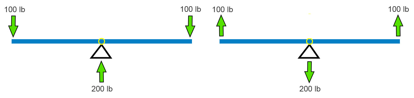
I’m going to stick will pull forces because they fit the bolt example better. A big kid and a little kid can still balance. Move the fulcrum toward the big kid (below left). The force the base pushes up with remains equal to the sum of the downward forces. This has to be in all cases. Newton (1st Law) must be satisfied.
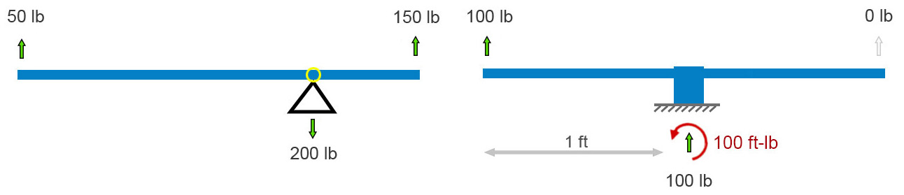
If the fulcrum – the pivot point – freezes up or is otherwise made immobile, the balancing act is no longer needed. The vertical forces still balance each other (cancel each other out), but now their is a twist on the base. Its left side wants to peel up. In addition to the sum of forces equaling zero, the sum of all twists must also sum to zero. A twist – I’ll use its physics name, moment – is defined as a force times the perpendicular distance through which it acts. In the above-right diagram, the 100 lb force is 1 foot from the base, so it applies a 100 ft-lb clockwise moment to the base (1 foot times 100 pounds = 100 ft-lb). (Notice we multiply the numbers and their units.) Therefore, to keep Isaac Newton happy, the ground must apply a 1 ft-lb counterclockwise moment (red curved arrow) to the base and beam that is fixed to it.
Anticipating a common point of confusion, I’ll point out here that, unlike the case where all the force arrows on this sort of “free body” diagram must sum to zero, there won’t necessarily be a visible curved arrow for every moment-balancing effect. Moment balance can exist between (1) a force times distance (100 lb up) and (2) a reaction moment (the counterclockwise moment applied by the ground), not between two drawn curved-arrows. If we focused on the ground and not the frozen see-saw, i.e., if we drew a free-body diagram of the ground and not the see-saw, we’d see a clockwise moment arrow representing the moment applied by the unbalanced base.
That’s all the pure statics we need to analyze these bolts. We’ll need mechanics of materials to analyze stresses. Let’s look at an idealized removable bolt in a hole. In particular, let’s look at an idealized Climbing Taiwan bolt. CT bolts have their integrated hangers welded to the bolt sleeve – fixed, like the base of the final see-saw above.
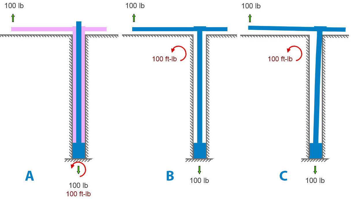
Figure A below shows an applied load of 100 pounds upward on the hanger. The bolt is anchored to rock at its base, at the bottom of the hole. A blue bolt is inside a pink hanger-sleeve assembly. The rock is pulling down on the base of the bolt with a force equal and opposite to the applied load. And the rock must apply a 100 ft-lb moment to the assembly to satisfy Newton. In figure A, it’s shown at the bottom of the hole.
But it need not be. Moments are global. Unlike forces, they aren’t applied at a point. We can move the curved arrow representing the moment – the twist the earth reacts to the load offset with – to any spot on the bolt assembly, as in the center diagram below. I further simplified the center diagram by removing the sleeve and modeling the situation as a single bolt-hanger assembly with space around it in the hole. For first-order calculations, given the small deflections involved, this simplification is acceptable. It helps us to see the key points.
We can allow the bolt to bend in the hole until it contacts the outside corner of the hole (figure B below). This changes very little besides adding some small counteracting horizontal forces there.
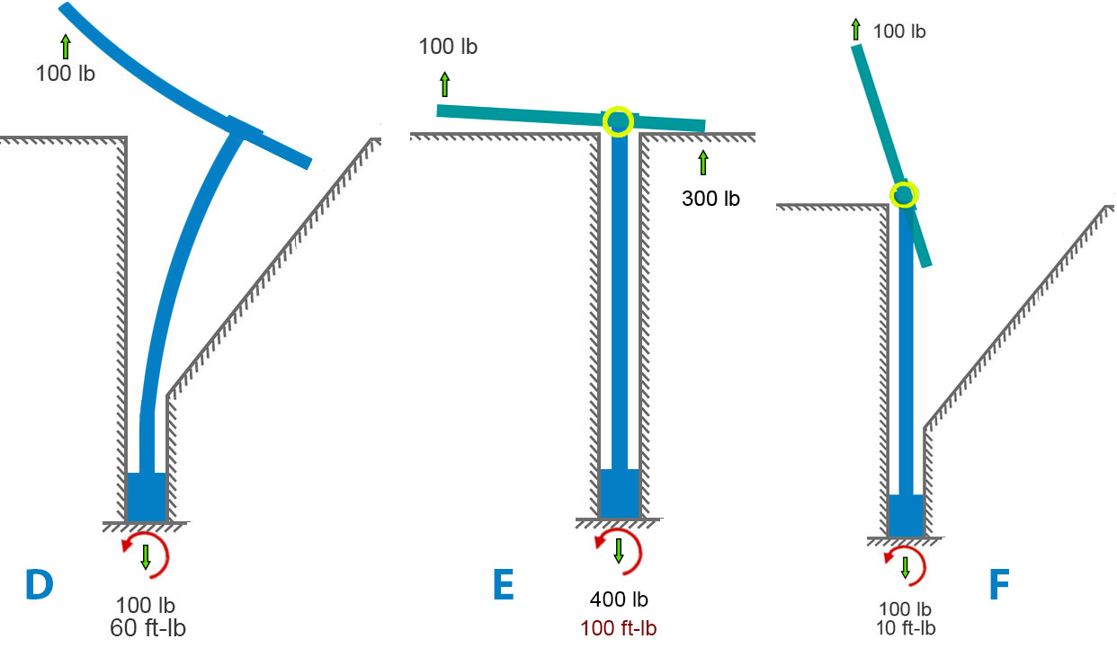
If we remove the rock and model a very bendy bolt, we get something like diagram D below. This leaves the forces unchanged but, in this extreme example, the moment is somewhat reduced because the moment arm (perpendicular distance between bolt and applied force) is considerably reduced by the bending.
We can also examine the case where the hanger is free to rotate on the bolt and sleeve (diagram E below). This is closer to the case of Petzl Pulse bolts. Here the 2nd-class lever mechanism comes into play. A “force-multiplier” is at work. If force-multiplier sounds like a bit of hand -waving, it is – forces aren’t multiplied per-se. We can do better and make Isaac Newton proud. A lever simply balances moments. If your hand is twice as far from the pivot as the load is, your hand needs only half the force because your longer distance gives your force more moment. Same moment, longer arm, smaller force. The 300-lb force at the hanger-rock (right side of bolt, figure E) contact exactly balances the 100-lb force that is three times farther away on the left side. Since both these forces pull upward on the hanger, the frictional force at the bottom of the whole becomes 400 pounds to balance it out. If no rock is on the right side of the hole, the hanger will rotate until it runs into something else (figure F).
Now we can look at stress, our bottom-line concern. Metal and rock and all other solids can take only so much stress, and then they break. For a material – say 304 steel – the stress at which it breaks is called its material strength. Material strength and stress are both measured in pounds per square inch (English) or Pascals (metric, often Megapascals, MPa). As a reference point, 304 steel breaks at a stress of 515 Mpa or 75,000 lb/sq-in. (75 ksi).
I will focus on figures A, B, C (identical for stress calcs), and E, since they are most like the real-world situations we’re concerned with. The various types of stresses all boil down to load divided by dimensions. Tensile stress is easy: axial load divided by cross sectional area. Since I’ve mixed English and metric units (for US reader familiarity), I’ll convert everything to metric units for stress calculation. Engineers use this symbol for stress: σ
Using σ = P/A to calculate axial stress, the numbers are:
- Axial load P= 100 lb =100 lbf = 444.82 N
- cross sectional area A = πd2/4 = 50.27 mm2
- radius c= 4 mm
Axial stress = σax = P/A = 8.85 MPa ≈ 1280 lb/sq-in.
The offset load imparts bending to the bolt. Calculating bending stress involves the concept of second moment of area (aka “cross-sectional moment of inertia” if you’re old-school). Many have tried to explain this concept simply. Fortunately, grasping its “why” is not essential to the point I want to make about axial vs. bending stress here. Nevertheless, here’s a short intro to the 2nd moment of area.
A beam under bending doesn’t care about how much material you have, it cares about how far that material is from the centerline. If you load a beam anchored at its ends in the middle, the top half (roughly) is in compression, the bottom half in tension. Top half squeezed, bottom stretched. Moment of area is a bookkeeping number that captures how much material you have times how far it sits from the centerline, squared. Add up every tiny patch of area, weighting each one by the square of its distance from the centerline. In shorthand, second moment of area (“I”) looks like this: I=∫y2dA
Now that you understand – or have taken on faith – the concept of second moment of area, we can calculate bending stress for the above scenario given the formula, σ = Mc/I.
Using σ = Mc/I, the numbers are:
- second moment I=πd4/64 = 201.06 mm4
- eccentric moment (i.e., the lever arm) = M = Pe=444.82 ⋅ 20 = 8896.44 N
Bending stress, σbend = Mc/I = 176.99 MPa ≈ 25,670 lb/sq-in.
The total stress of the bolt depends on which side of the bolt we are looking at. The maximum tensile stress is on the side that is getting stretched both by the applied axial load (100 lb) and by the fact that this load is offset. On that side of the bolt, we just add the axial and bending stress components (on the other side we would subtract the bending):
σtotal = σax ± σbend = 8.85 MPa + 176.99 MPa = 185.84 MPa ≈ 26,950 lb/sq-in.
Here we see something startling to folk who don’t do this kind of work. For situations like bolts and fasteners, the stress component due to the pullout force with no offset is insignificant compared to the effect of the offset. Bending completely dominates. By a factor of twenty in this case. Increasing the pure axial stress by increasing the applied axial load has little effect on the total stress in the bolt.
If we compare the A/B/C models with the E model, the pure-axial component grows by 18 MPa because of the higher reactive tensile force:
σtotal = σax ± σbend = 26.55 MPa + 176.99 MPa = 203.54 MPa ≈ 29521 lb/sq-in.
Adding the sleeve back to the model changes very little. It would reduce the force-multiplier effect in case E (thereby making it closer to A, B, and C) for several reasons that would take a lot of writing to explain well.
In the case of axially loaded removable bolts (not the use-case for which they were designed – significantly) the offset axial load greatly increases (completely dominates, in fact) the stress in the bolt. When a bolt carries an axial load that’s offset from its centerline, the problem isn’t any leverage created by the hanger’s prying geometry. That leverage effect is trivial. The offset itself produces a bending moment, and that bending drives the stress. For slender round members like bolts, bending overwhelms everything else.
Furthermore, published pull tests and my analysis of rock-limited vs. bolt-limited combinations of bolt diameter, length and rock strength suggest that bolt stress/strength is not a useful criterion for selecting removables. Based on what I’ve seen and experienced so far, I find the CT removables superior to other models for my concerns – durability, maintainability, reducing rock stress, and most importantly, ensuring that the wedge engages the back of the hole.
