Archive for category Engineering & Applied Physics
Removable Climbing Bolt Stress Under Offset Loading
Posted by Bill Storage in Engineering & Applied Physics on November 13, 2025
A Facebook Group has been discussing how load direction affects the stress state of removable bolts and their integral hangers. Hanger geometry causes axial loads to be applied with a small (~ 20mm) offset from the axis of the bolt. One topic of discussion is whether this offset creates a class-2 leverage effect, thereby increasing the stress in the bolt. Other aspects of the physics of these bolts warrant discussion. This can serve as a good starter, specifically addressing the leveraging/prying concern.
Intuition is a poor guide for this kind of problem. Nature doesn’t answer to consensus or gut feeling, and social reasoning won’t reveal how a bolt actually behaves. The only way to understand what’s happening is to go back to basic physics. That’s not a criticism of anyone’s judgment, it’s just the boundary the world imposes on us.
Examining the problem starts with simple physics (statics). Then you need to model how the system stretches and bends. You need to look at its stress state. So you need to calculate. A quick review of the relevant basics of mechanics might help. They are important to check the validity of the mental models we use to represent the real-world situation.
The classic balanced see-saw is at left below. The two 100 lb weights balance each other. The base pushes up on the beam with 200 pounds. We see Newton’s 1st Law in action. Sum of the down forces = sum of the up forces. If we say up forces are positive and down are negative, all the forces on the beam sum to zero. Simple. The see-saw works in tension too. Pull up with 2 ⋅ 100 pounds and the base pulls down by the same amount.
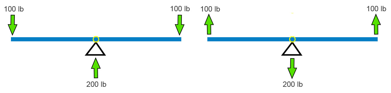
I’m going to stick will pull forces because they fit the bolt example better. A big kid and a little kid can still balance. Move the fulcrum toward the big kid (below left). The force the base pushes up with remains equal to the sum of the downward forces. This has to be in all cases. Newton (1st Law) must be satisfied.
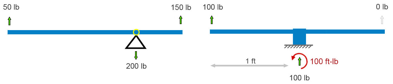
If the fulcrum – the pivot point – freezes up or is otherwise made immobile, the balancing act is no longer needed. The vertical forces still balance each other (cancel each other out), but now their is a twist on the base. Its left side wants to peel up. In addition to the sum of forces equaling zero, the sum of all twists must also sum to zero. A twist – I’ll use its physics name, moment – is defined as a force times the perpendicular distance through which it acts. In the above-right diagram, the 100 lb force is 1 foot from the base, so it applies a 100 ft-lb clockwise moment to the base (1 foot times 100 pounds = 100 ft-lb). (Notice we multiply the numbers and their units.) Therefore, to keep Isaac Newton happy, the ground must apply a 1 ft-lb counterclockwise moment (red curved arrow) to the base and beam that is fixed to it.
Anticipating a common point of confusion, I’ll point out here that, unlike the case where all the force arrows on this sort of “free body” diagram must sum to zero, there won’t necessarily be a visible curved arrow for every moment-balancing effect. Moment balance can exist between (1) a force times distance (100 lb up) and (2) a reaction moment (the counterclockwise moment applied by the ground), not between two drawn curved-arrows. If we focused on the ground and not the frozen see-saw, i.e., if we drew a free-body diagram of the ground and not the see-saw, we’d see a clockwise moment arrow representing the moment applied by the unbalanced base.
That’s all the pure statics we need to analyze these bolts. We’ll need mechanics of materials to analyze stresses. Let’s look at an idealized removable bolt in a hole. In particular, let’s look at an idealized Climbing Taiwan bolt. CT bolts have their integrated hangers welded to the bolt sleeve – fixed, like the base of the final see-saw above.
Figure A below shows an applied load of 100 pounds upward on the hanger. The bolt is anchored to rock at its base, at the bottom of the hole. A blue bolt is inside a pink hanger-sleeve assembly. The rock is pulling down on the base of the bolt with a force equal and opposite to the applied load. And the rock must apply a 100 ft-lb moment to the assembly to satisfy Newton. In figure A, it’s shown at the bottom of the hole.
But it need not be. Moments are global. Unlike forces, they aren’t applied at a point. We can move the curved arrow representing the moment – the twist the earth reacts to the load offset with – to any spot on the bolt assembly, as in the center diagram below. I further simplified the center diagram by removing the sleeve and modeling the situation as a single bolt-hanger assembly with space around it in the hole. For first-order calculations, given the small deflections involved, this simplification is acceptable. It helps us to see the key points.
We can allow the bolt to bend in the hole until it contacts the outside corner of the hole (figure B below). This changes very little besides adding some small counteracting horizontal forces there.
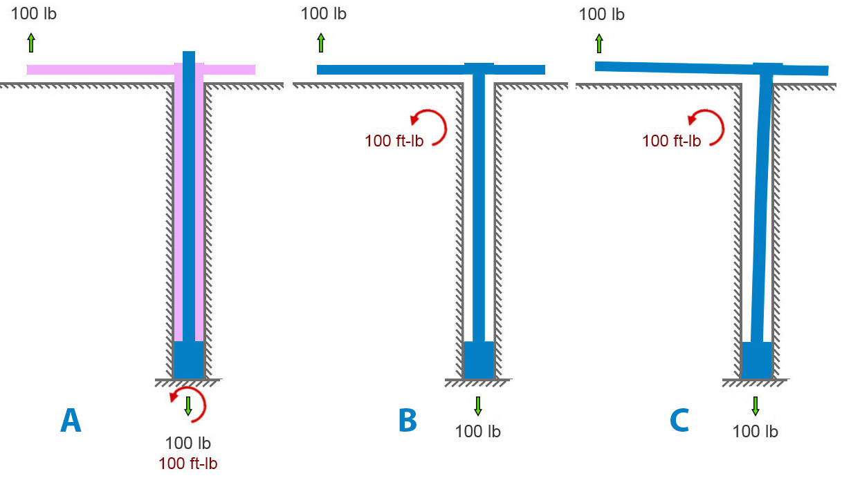
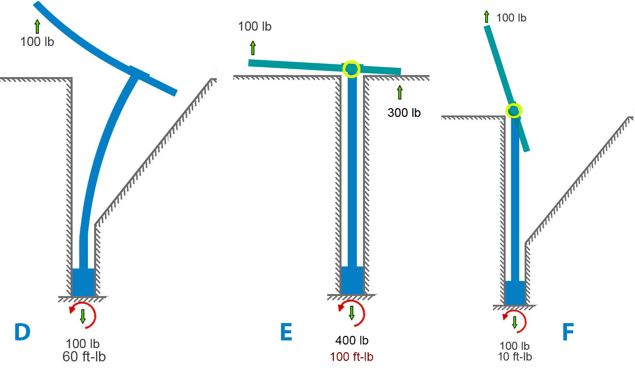
If we remove the rock and model a very bendy bolt, we get something like diagram D below. This leaves the forces unchanged but, in this extreme example, the moment is somewhat reduced because the moment arm (perpendicular distance between bolt and applied force) is considerably reduced by the bending.
We can also examine the case where the hanger is free to rotate on the bolt and sleeve (diagram E below). This is closer to the case of Petzl Pulse bolts. Here the 2nd-class lever mechanism comes into play. A “force-multiplier” is at work. If force-multiplier sounds like a bit of hand -waving, it is – forces aren’t multiplied per-se. We can do better and make Isaac Newton proud. A lever simply balances moments. If your hand is twice as far from the pivot as the load is, your hand needs only half the force because your longer distance gives your force more moment. Same moment, longer arm, smaller force. The 300-lb force at the hanger-rock (right side of bolt, figure E) contact exactly balances the 100-lb force that is three times farther away on the left side. Since both these forces pull upward on the hanger, the frictional force at the bottom of the whole becomes 400 pounds to balance it out. If no rock is on the right side of the hole, the hanger will rotate until it runs into something else (figure F).
Now we can look at stress, our bottom-line concern. Metal and rock and all other solids can take only so much stress, and then they break. For a material – say 304 steel – the stress at which it breaks is called its material strength. Material strength and stress are both measured in pounds per square inch (English) or Pascals (metric, often Megapascals, MPa). As a reference point, 304 steel breaks at a stress of 515 Mpa or 75,000 lb/sq-in. (75 ksi).
I will focus on figures A, B, C (identical for stress calcs), and E, since they are most like the real-world situations we’re concerned with. The various types of stresses all boil down to load divided by dimensions. Tensile stress is easy: axial load divided by cross sectional area. Since I’ve mixed English and metric units (for US reader familiarity), I’ll convert everything to metric units for stress calculation. Engineers use this symbol for stress: σ
Using σ = P/A to calculate axial stress, the numbers are:
- Axial load P= 100 lb =100 lbf = 444.82 N
- cross sectional area A = πd2/4 = 50.27 mm2
- radius c= 4 mm
Axial stress = σax = P/A = 8.85 MPa ≈ 1280 lb/sq-in.
The offset load imparts bending to the bolt. Calculating bending stress involves the concept of second moment of area (aka “cross-sectional moment of inertia” if you’re old-school). Many have tried to explain this concept simply. Fortunately, grasping its “why” is not essential to the point I want to make about axial vs. bending stress here. Nevertheless, here’s a short intro to the 2nd moment of area.
A beam under bending doesn’t care about how much material you have, it cares about how far that material is from the centerline. If you load a beam anchored at its ends in the middle, the top half (roughly) is in compression, the bottom half in tension. Top half squeezed, bottom stretched. Moment of area is a bookkeeping number that captures how much material you have times how far it sits from the centerline, squared. Add up every tiny patch of area, weighting each one by the square of its distance from the centerline. In shorthand, second moment of area (“I”) looks like this: I=∫y2dA
Now that you understand – or have taken on faith – the concept of second moment of area, we can calculate bending stress for the above scenario given the formula, σ = Mc/I.
Using σ = Mc/I, the numbers are:
- second moment I=πd4/64 = 201.06 mm4
- eccentric moment (i.e., the lever arm) = M = Pe=444.82 ⋅ 20 = 8896.44 N
Bending stress, σbend = Mc/I = 176.99 MPa ≈ 25,670 lb/sq-in.
The total stress of the bolt depends on which side of the bolt we are looking at. The maximum tensile stress is on the side that is getting stretched both by the applied axial load (100 lb) and by the fact that this load is offset. On that side of the bolt, we just add the axial and bending stress components (on the other side we would subtract the bending):
σtotal = σax ± σbend = 8.85 MPa + 176.99 MPa = 185.84 MPa ≈ 26,950 lb/sq-in.
Here we see something startling to folk who don’t do this kind of work. For situations like bolts and fasteners, the stress component due to the pullout force with no offset is insignificant compared to the effect of the offset. Bending completely dominates. By a factor of twenty in this case. Increasing the pure axial stress by increasing the applied axial load has little effect on the total stress in the bolt.
If we compare the A/B/C models with the E model, the pure-axial component grows by 18 MPa because of the higher reactive tensile force:
σtotal = σax ± σbend = 26.55 MPa + 176.99 MPa = 203.54 MPa ≈ 29521 lb/sq-in.
Adding the sleeve back to the model changes very little. It would reduce the force-multiplier effect in case E (thereby making it closer to A, B, and C) for several reasons that would take a lot of writing to explain well.
In the case of axially loaded removable bolts (not the use-case for which they were designed – significantly) the offset axial load greatly increases (completely dominates, in fact) the stress in the bolt. When a bolt carries an axial load that’s offset from its centerline, the problem isn’t any leverage created by the hanger’s prying geometry. That leverage effect is trivial. The offset itself produces a bending moment, and that bending drives the stress. For slender round members like bolts, bending overwhelms everything else.
Furthermore, published pull tests and my analysis of rock-limited vs. bolt-limited combinations of bolt diameter, length and rock strength suggest that bolt stress/strength is not a useful criterion for selecting removables. Based on what I’ve seen and experienced so far, I find the CT removables superior to other models for my concerns – durability, maintainability, reducing rock stress, and most importantly, ensuring that the wedge engages the back of the hole.
Climbing Taiwan Removable Bolts Review
Posted by Bill Storage in Engineering & Applied Physics on November 6, 2025
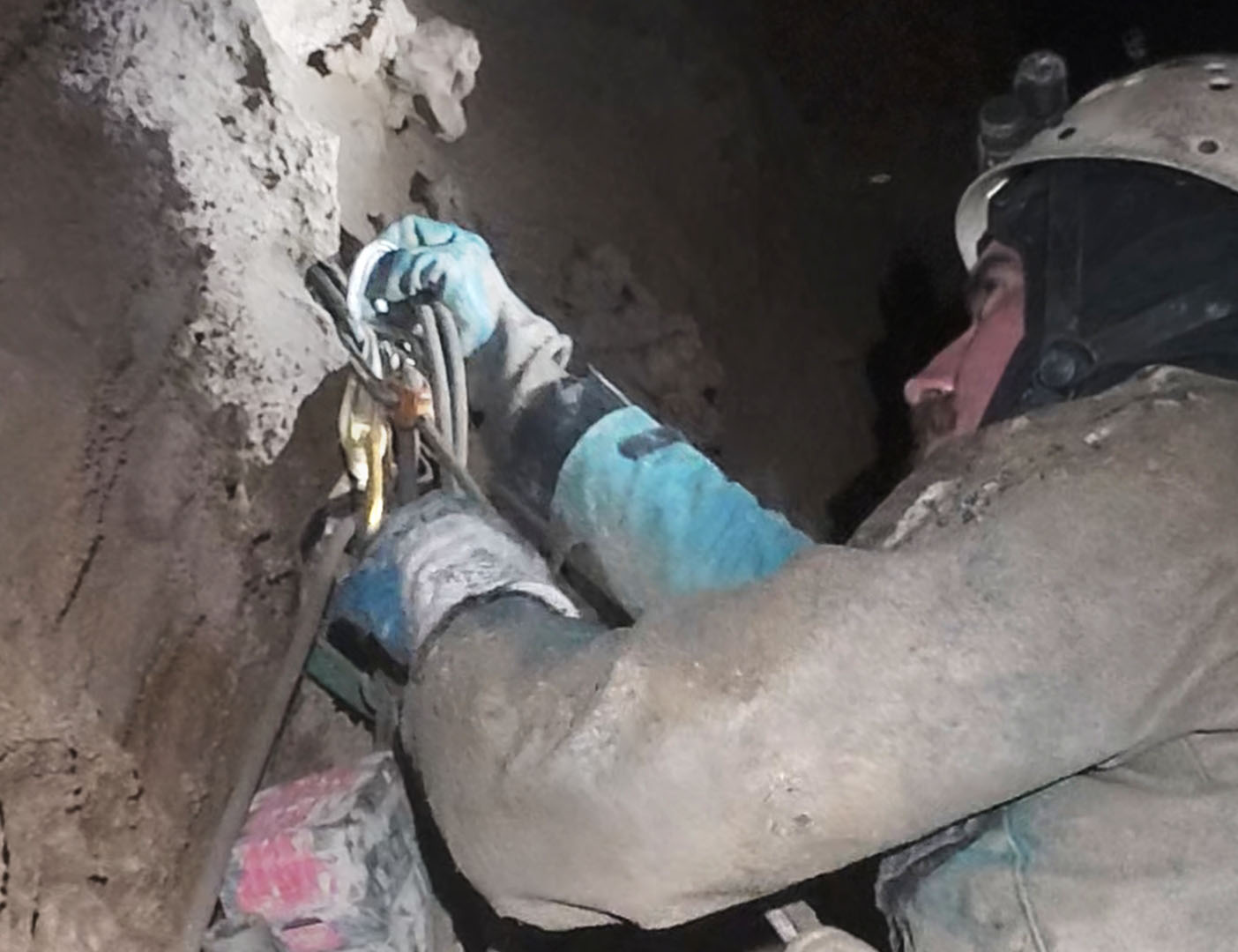
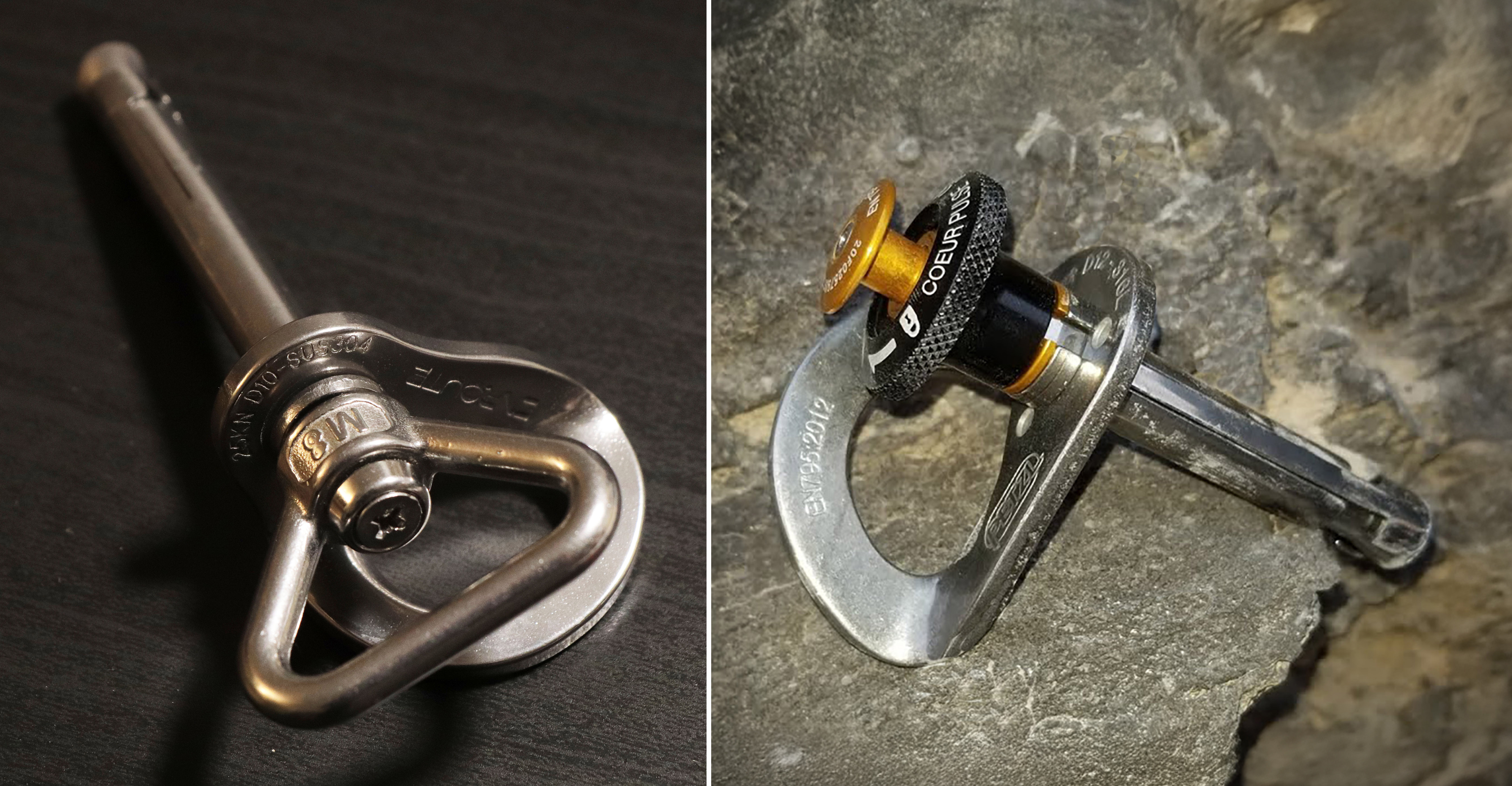
Friends and I have been experimenting with removable bolts in muddy caves, and many of us have been concerned about the robustness of the devices. I don’t mean their strength. They’re plenty strong. I mean how well do they hold up in a cave environment – and can we be ensured of a good placement. I just got some new removable bolts from Climbing Taiwan (CT). Compared to the Petzl Pulse design, which have proven to be finicky in caves, they look like they might be better suited for use in cave environments.
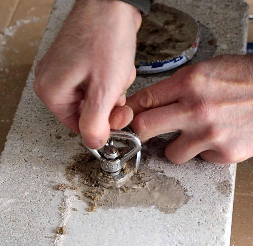
I don’t have a cave or a hammer drill on hand right now, so I put a 10mm masonry bit in my handheld driver and drilled holes in a concrete block to test the bolts.
For this testing I wanted to drill the hole barely long enough to fit the bolt in – against the recommendations of the manufacturer. I wanted to experiment with the consequences of crud in the bottom of the hole.
Normally, with 3/8 and 10mm bolts wedge bolts wedge bolts I don’t blow out the holes or brush them underground. I merely withdraw the drill with it rotating slightly and pull the dust out of the hole. I’ve placed hundreds of bolts and have never had a spinner. I torque my 3/8 wedge bolts to 25 foot pounds underground.
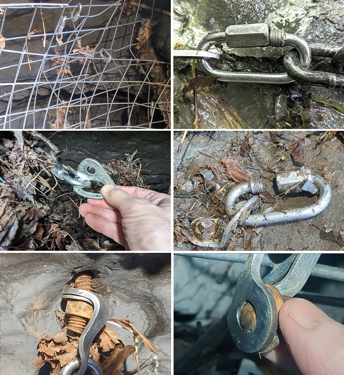
Because, for these tests, I am drilling vertically downward and I am using a masonry bit instead of a hammer drill bit, I had to brush the dust out of these holes. I did not use a blow tube. This is really bad bolting hygiene. I wanted to see if I could gum up the works. I am intentionally using these removable bolts wrong, against the advice of the manufacturer, and against good sense.
To simulate the abuse that bolts take underground, I first mixed the concrete dust with water and packed it onto the bolt mechanism. Then I poured the sludge into the hole.
Then I added sand to the mix. I packed on as much sand as I could. I also tried getting sand into the threads at the top of the hanger. This proved no problem for installation or removal. I then pushed sand into the hole to see if I could force the wedge through the sand sludge and back toward the outside of the hole.
For the next simulation of cave mud I combined honey and cornstarch. Wet corn starch is fun to use in these experiments because it is a non-euclidean fluid with some odd properties. I again added sand. I then smeared the cornstarch honey sand combination along the sleeve and the threaded region.
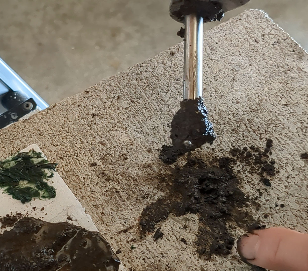
For the next test I got a fresh cylinder of clay- rich mud and added it to the mix. The bolt and the sludge clearly filled the entire hole as is visible by the overflow. I did the same with a mix of plumber’s grease and garden dirt. Again, no problem.
I used a pressure washer to clean them. I took them apart to be sure. Good as new.
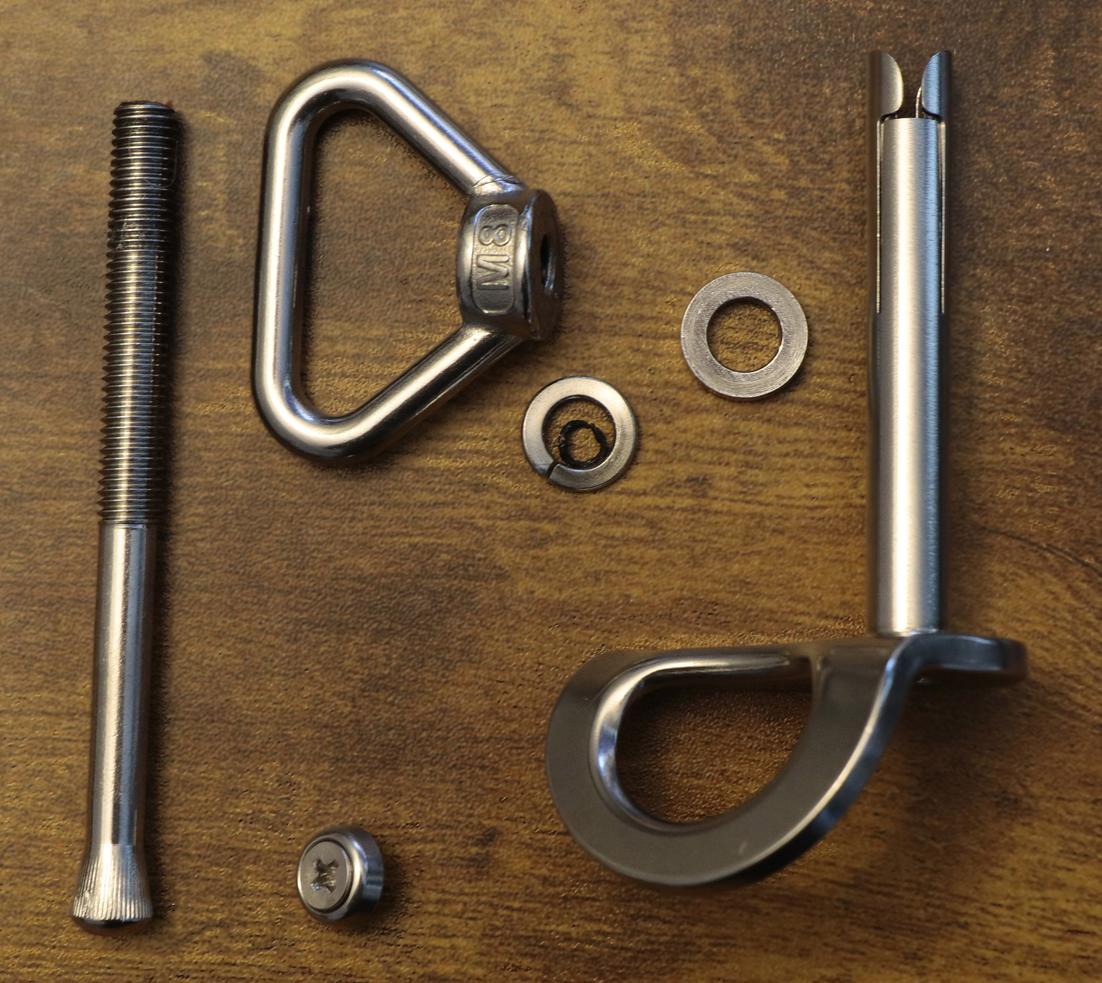
The manufacturer says they used 2205 stainless steel for the threaded shaft and 304 for everything else. These are smart choices that reflect sound engineering. 304 is very widely used. It’s machinable and has high ductility. Its ultimate strength is several times higher than its yield strength. It is extremely forgiving and has excellent corrosion resistance. Duplex 2205 is much stronger, much more expensive, and has some trade-offs (like weldability), none of which are at all relevant to this usage.
I tested the components for ferromagnetism. In theory, 304 alloy hangers should not be magnetic. OK, little bit of engineering here. 304 is austenitic; its atoms are arranged in a body-centered cubic structure. But when you cut or beat on austenitic stainless, you can cause some degree of room-temperature phase transformation. A room-temperature crystalline phase change always seemed like magic to me, but it happens. Ancient blacksmiths were similarly amazed. This cold-working causes atoms to jump into a body-centered tetragon pattern called martensite, which is magnetic. It also causes carbon atoms to bunch up a bit, and this can reduce corrosion life.
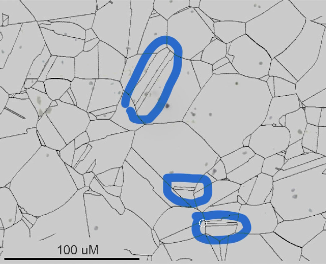
But these bolts are not intended as permanent anchors. And when I look at the hangers under a scope at 250x, I see maybe a couple of percent martensite. Rough calculation of the life of a 304 bolt in a typical Appalachian cave with no brine and low chlorides yields a range of about 1000 to 20,000 years. If we shift that bolt into its martensitic state, we’d reduce its life in a cave down to maybe 50 to 1,000 years. But that is for full martensite, and I’m seeing only a percent or two. In other words, we can ignore the fact that this hanger is slightly magnetic. The Duplex 2205 threaded shaft (“duplex” because it is part ferrite, part austenite – elongated austenite grains in a ferritic matrix, so it is magnetic), since it isn’t welded or otherwise altered, would have a corrosion life of 2 to 5 times that of 304.
I measured hardness at Rockwell C25 – around 90,000 psi – a bit higher than you’d expect for annealed 304, but consistent with the cold working that resulted in the magnetism. Totally inconsequential.
I generally don’t do destructive testing. It’s usually pointless or worse. It’s entertaining to watch gear break, but focusing on ultimate strength just encourages dangerous misconceptions. Safety in climbing gear depends on how forces are distributed, how materials deform, and, mostly, how elasticity affects the system – how energy is absorbed. The inelasticity of a static rope that’s stronger than a dynamic rope can kill you. F=ma and F=kx are not just equations – they are life-and-death considerations.
I like to look at the underlying physics, and highlight what matters in practical use. My goal is to give climbers accurate, responsible insight – not spectacle – and to counter the intuition that ‘stronger = safer.’ This approach is personal to me as well: a close friend died while aid climbing in a cave because he misunderstood these principles. We might honor his memory by helping others understand how stuff works.
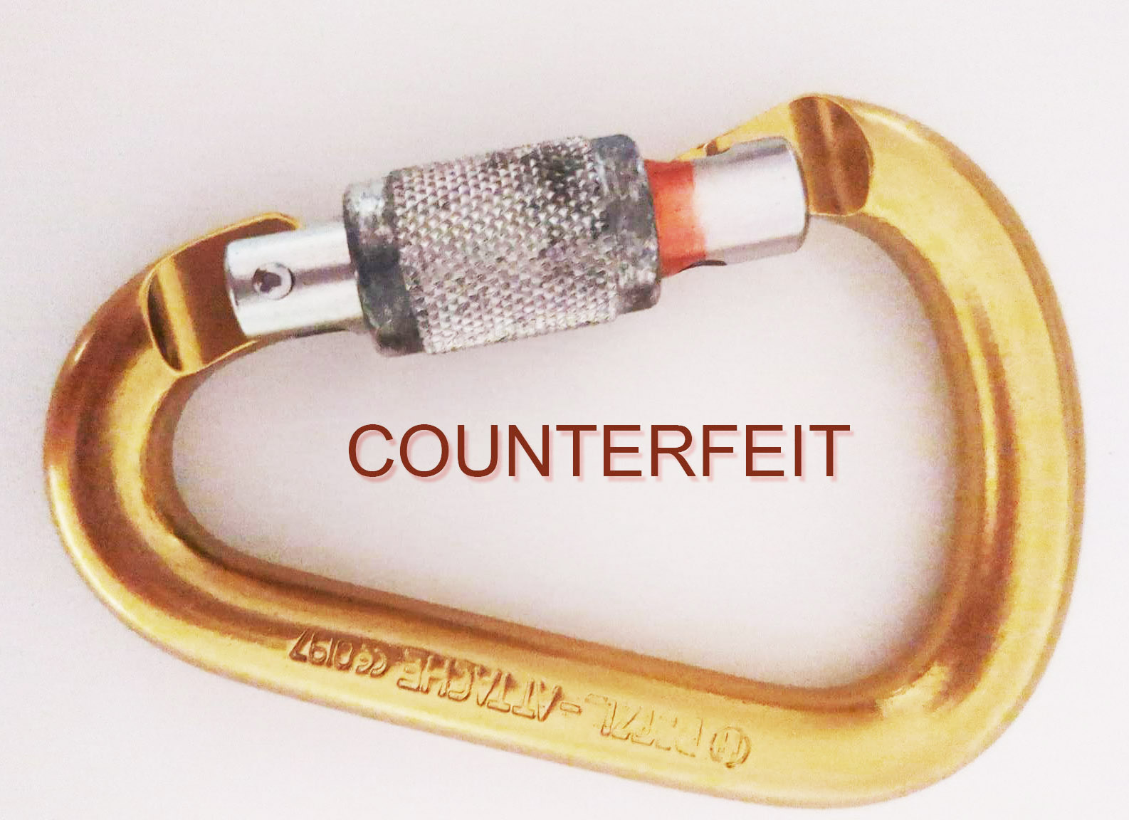
Why not break them? The removable-bolt components – bolts and hangers – are made from standard engineering materials, like 304. These materials are mass-produced in sheet and rod form, and have extremely low likelihood of defects. 304 stainless is not a cottage-industry alloy. Producing it requires integrated melt, alloying, and forging infrastructure with tight control of composition and processing. You can’t fake it cheaply. So the global quality variation for 304 is extremely narrow compared to, say, low-alloy steels, bronze, or, unfortunately for cavers, aluminum castings and forgings. Counterfeit carabiners. But that’s another article.
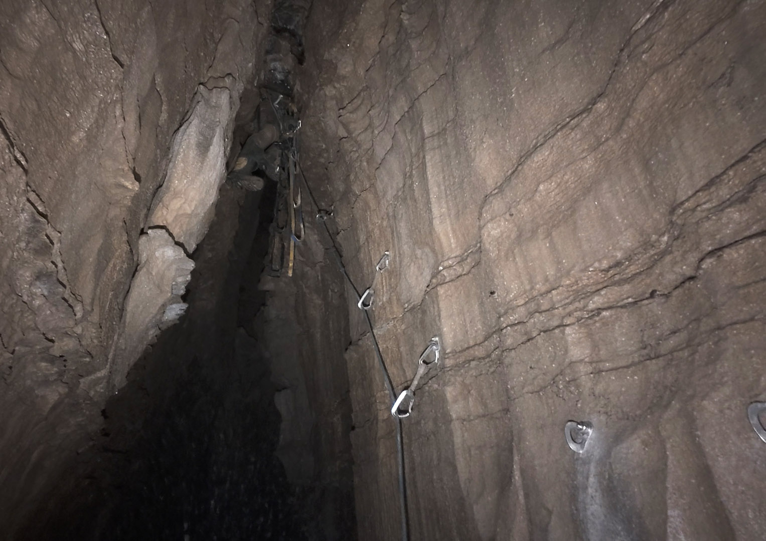
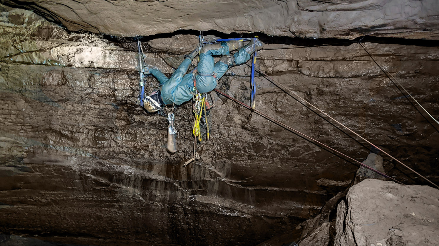
Breaking these bolts on video would add zero real information. Their strength far exceeds what a human body can impose or withstand. What actually matters – the rock quality, technique, and proper installation – is rarely tested or demonstrated on YouTube. If there is concern about a manufacturer’s integrity, destructive testing of one or two bolts is meaningless. Instead, careful microstructural examination and non-destructive testing across a larger sample set provide meaningful insight, without teaching viewers some sort of cargo-cult science. Removable bolts are intended for shear loading only. Think standard aid climbs, not ones like this:
But any real-world usage involves some amount of axial load. Tests on other removable bolts show them to have very high strength in the axial direction. Usually, the rock blows out first.
The fact that the rock usually blows out first points to another advantage of these Climbing Taiwan bolts over the Petzl. In soft rock, bolt length trumps bolt diameter because rock strength dominates. The 3-inch, 10mm diameter CT bolt vs. the 2 and a quarter inch Petzl 12mm. In hard rock, bolt strength dominates, but in hard rock, the breaking strength for both 10 and 12mm far exceed survivability. This is a perfect example of where destructive testing results will lead you to the wrong conclusion.
With a few assumptions, we can easily calculate the relative performance of the Pulse and the CT bolts loaded in shear:
Sleeve / shaft sizes
- Pulse: sleeve Ø = 12.0 mm, shaft Ø = 10.0 mm, embed length = 55 mm
- CT (10 mm): sleeve Ø = 10.0 mm, shaft Ø = 8.0 mm, embed length = 77 mm.
- Material strengths (conservative working numbers)
- Sleeve material 304 stainless, UTS = 520 MPa. Shear strength = 0.6·UTS = 312 MPa.
- Shaft material 2205 duplex, UTS = 860 MPa. Shear strength = 0.6·UTS = 516 MPa.
- Use the shaft shear (2205) as the bolt shear limit.
- Two limiting modes considered, and the lower one governs:
For rock-limited shear:
Rock shear strength × lateral contact area of the sleeve (projected cylindrical area = π·d_sleeve·embed_length). This models shear/punching or interface shear of the sleeve against rock.
For bolt (shaft) shear:
Material shear strength × cross-sectional area of the shaft (π·d^2/4). This models a straight shear through the shaft.
No complex friction, bending, or stress concentrations included. This is a first-order, worst-case shear capacity comparison.
| Rock shear strength | Pulse 12 mm, embed 55 mm | CT 10 mm, embed 77 mm |
| 1000 psi | rock limit 14.30 kN (3,214 lb) bolt limit 40.53 kN (9,111 lb) | rock limit 16.68 kN (3,761 lb) bolt limit 25.94 kN (5,831 lb) |
| 2000 psi | rock limit 28.59 kN (6,428 lb) bolt limit 40.53 kN (9,111 lb) | rock limit 33.36 kN (7,523 lb) bolt limit 25.94 kN (5,831 lb) |
| 4000 psi | rock limit 57.18 kN (12,855 lb) bolt limit 40.53 kN (9,111 lb) | rock limit 66.71 kN (14,998 lb) bolt limit 25.94 kN (5,831 lb) |
To evaluate the sensitivity of this model to assumptions, we can make the following changes, aiming at higher conservatism:
- 2205 duplex shear taken as 0.5·UTS, i.e. 430 MPa.
- A conservative Rock-punching reduction factor of 0.6 applied to the nominal rock shear strength to model local failure modes, stress concentrations, and imperfect contact.
| Rock shear strength | Pulse 12 mm, embed 55 mm | CT 10 mm, embed 77 mm |
| 1000 psi | rock limit 8.58 kN (1,928 lb) bolt limit 33.77 kN (7,592 lb) | rock limit 10.01 kN (2,250 lb) bolt limit 21.61 kN (4,859 lb) |
| 2000 psi | rock limit 17.16 kN (3,857 lb) bolt limit 33.77 kN (7,592 lb) | rock limit 20.01 kN (4,499 lb)bolt limit 21.61 kN (4,859 lb) |
| 4000 psi | rock limit 34.31 kN (7,713 lb) bolt limit 33.77 kN (7,592 lb) | rock limit 40.03 kN (8,999 lb) bolt limit 21.61 kN (4,859 lb) |
This results in lower strength values for both rock and bolt, but the relationships and conclusions still stand. In weak rock, length trumps diameter; in strong rock, bolt strength dominates but both 10 and 12mm strengths are far above survivability. The below chart plots governing capacity vs nominal rock shear to show the crossover points:
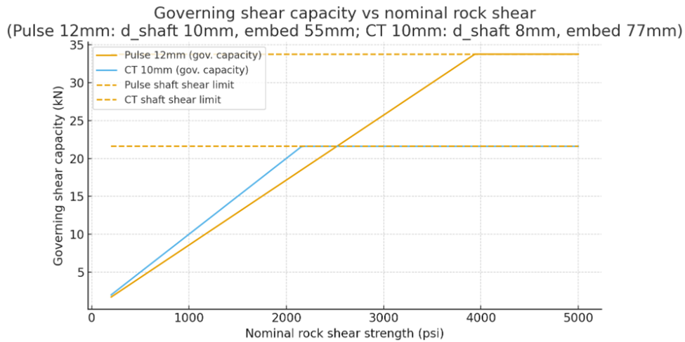
So my conclusion that the CT bolts are better designed for cave rock than the Petzl Pulses is not sensitive to assumptions about Rock-punching reduction factor or the relationship between 2205’s ultimate tensile and ultimate shear strength. The CT bolts come out looking like a better design for cave rock (and, of course, neither was designed for use in caves).
It’s also worth noting that the longer 10mm CT bolt removes 10 percent less rock than the shorter 12mm Petzl bolt. So you’re getting about 10% more bolting per battery.
Returning to axial strength. Because the core principle at work in these bolts is lateral expansion under confinement (a radial pressure multiplier from a low-angle taper), we need to control the hole diameter to achieve the needed confinement. These Climbing Taiwan bolts allow you to torque them down – in a sense. This isn’t torquing to achieve tensile preload, as in wedge anchors. It is about mechanically setting the wedge to the local bore diameter. Think of it like calibrating the anchor to the hole. You can expand the sleeve using the handle until you feel firm engagement. That lets you tune for real-world variability in hole diameter, rock roughness, or small flares and cracks. That seems to me the big advantage of this design; it’s more tolerant of the wobbly drilling that sub-optimal cave settings often give us.
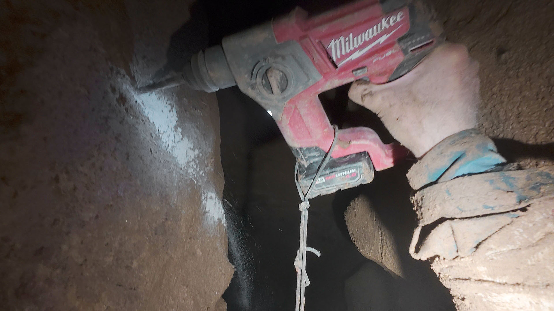
Beyond being easier to clean and having superior strength in soft rock compared to the 12mm Petzl Pulse, the cleverness here is in better decoupling hole-fit adjustment from load resistance. I was able to engage the nominally 10mm bolt in a 12mm diameter hole. I’ll still avoid drilling bad holes, but this is very good to know, especially when drilling in confined or awkward places where suddenly the little Milwaukee decides to go on a rotary rampage.
If you have experience with these underground, or have questions or comments, please feel free to add a comment below. Sometimes I miss real engineering.
Physics for Cold Cavers: NASA vs Hefty and Husky
Posted by Bill Storage in Engineering & Applied Physics on October 21, 2025
In the old days, every caver I knew carried a space blanket. Many still do. They come vacuum-packed in little squares that look like tea bricks, promising to help prevent hypothermia. They were originally marketed as NASA technology – because, in fact, they were. The original Mylar “space blanket” came out of the 1960s U.S. space program, meant to keep satellites and astronauts thermally stable in the vacuum of orbit. They reflected infrared radiation superbly, but only because they were surrounded by nothing. In a cave, you’re surrounded by something – cold, wet air – and that’s a very different problem.
A current ad says:
Reflects up to 90% of body heat to help prevent hypothermia and maintain core temperature during emergencies.
Another says:
Losing body heat in emergencies can quickly lead to hypothermia. Without understanding the science behind thermal protection, you might not use these tools effectively when they’re needed most.
This is your standard science-washing, techno-fetish, physics-theater advertising. Feynman called it cargo-cult science. But even Google Gemini told me:
For a vapor barrier in an emergency, a space blanket is better than a trash bag because it reflects radiant heat.
Premise true, conclusion false – non sequitur, an ancient Roman would say. It seems likely that advertising narratives played a quiet role in Google’s large-model-based AI system’s space-blanket blunder. That’s a topic for another time I guess.
Back to cold reality. At 50 degrees and 100 percent humidity, radiative heat loss is trivial. Radiative transfer at 10–15°C delta T is a rounding error compared to where your heat really goes. What matters is conduction to damp rock and convection to moving air, both of which a shiny sheet does little to stop. Worse, a rectangle of Mylar always leaks. Every fold and corner is a draft path, and soon you’re sitting in a crinkling echo chamber, shivering and reflecting nothing but a bad decision.
The contractor-size trash bag, meanwhile, is an unsung hero of survival. Poke a face hole near the bottom, pull it over your head, and you have a passable poncho that sheds drips instead of channeling them down your collar. You can sit on it, wrap your feet, and trap a pocket of warm, humid air that actually slows heat loss. Let a little moisture vent, and it works for an hour or two without turning clammy.
The space blanket survives mostly on myth – the glamour of NASA and the gleam of techno-hype. The homely trash bag simply works – better than anything near its size will. One was made for space, the other for the world we actually live in. Losing body heat in emergencies can quickly lead to hypothermia. Without getting the basics of thermal protection, you might not pick the best tool.
—
For those who need the physics, read on…
Heat leaves the body by three routes: conduction, convection, and radiation. Conduction is direct contact – warm skin meeting cool air, damp limestone, and mud. Convection is moving air stealing that warmed boundary layer and replacing it with fresh, cold air. Warm air is lighter. You warm the nearby air. It rises and sucks in fresh, cooler air. A circulating current arises.
At 50°F in a cave, conduction and convection dominate. The air is dense and wet, which means excellent thermal coupling. Each tiny current of air wicks warmth away far more effectively than dry air would. A trash bag stops that process cold. By trapping a thin layer of air and sealing it from drafts, it cuts off convective loss almost completely. It also slows conductive loss because still air, though not as good as down, is a decent insulator.
Radiation is infrared energy emitted from your skin and clothing into the surroundings. It follows the Stefan–Boltzmann law: power scales with the fourth power of absolute temperature. That sounds dramatic until you run the numbers. Between an 85°F body (skin temperature, roughly, 300° Kelvin) and a 50°F cave wall, the difference is about 27 Kelvin.
q = σ T4 A where q is heat transfer per unit time, T is temperature difference in Kelvins, and A is the radiative area.
Plug it in, and the radiative loss is about one percent of total heat loss – barely measurable compared to what you’re losing through air movement. The “90 percent reflection” claim is technically true in a vacuum, but in a cave or in Yosemite it’s a rounding error dressed up as science.
So the short version: the shiny Mylar sheet reflects an irrelevant component of heat loss while ignoring the main ones. The humble and opaque trash bag attacks the real physics of staying warm. It doesn’t sparkle, it gets the job done.
I’m Only Neurotic When – Engineering Edition
Posted by Bill Storage in Commentary, Engineering & Applied Physics on October 7, 2025
The USB Standard of Suffering
The USB standard was born in the mid-1990s from a consortium of Intel, Microsoft, IBM, DEC, NEC, Nortel, and Compaq. They formed the USB Implementers Forum to create a universal connector. The four pins for power and data were arranged asymmetrically to prevent reverse polarity damage. But the mighty consortium gave us no way to know which side was up.
The Nielsen Norman Group found that users waste ten seconds per insertion. Billions of plugs times thirty years. We could have paved Egypt with pyramids. I’m not neurotic. I just hate death by a thousand USB cuts.
The Dyson Principle
I admire good engineering. I also admire honesty in materials. So naturally, I can’t walk past a Dyson vacuum without gasping. The thing looks like it was styled by H. R. Giger after a head injury. Every surface is ribbed, scooped, or extruded as if someone bred Google Gemini with CAD software, provided the prompt “manifold mania,” and left it running overnight. Its transparent canister resembles an alien lung. There are ducts that lead nowhere, fins that cool nothing, and bright colors that imply importance. It’s all ornamental load path.
To what end? Twice the size and weight of a sensible vacuum, with eight times the polar moment of inertia. (You get the math – of course you do.) You can feel it fighting your every turn, not from friction, but from ego. Every attempt at steering carries the mass distribution of a helicopter rotor. I’m not cleaning a rug, I’m executing a ground test of a manic gyroscope.
Dyson claims it never loses suction. Fine, but I lose patience. It’s a machine designed for showroom admiration, not torque economy. Its real vacuum is philosophical: the absence of restraint. I’m not neurotic. I just believe a vacuum should obey the same physical laws as everything else in my house. I’m told design is where art meets engineering. That may be true, but in Dyson’s case, it’s also where geometry goes to die. There’s form, there’s function, and then there’s what happens when you hire a stylist who dreams in centrifugal-manifold Borg envy.
Frank Lloyd Wright’s Physics
No one but Frank Lloyd Wright could have designed these cantilevered concrete roof supports, the tour guide at the Robie House intoned reverently, as though he were describing Moses with a T-square. True – and Mr. Wright couldn’t have either. The man drew poetry in concrete, but concrete does not care for poetry. It likes compression. It hates tension and bending. It’s like trying to make a violin out of breadsticks.
They say Wright’s genius was in making buildings that defied gravity. True in a sense – but only because later generations spent fifty times his budget figuring ways to install steel inside the concrete so gravity and the admirers of his genius wouldn’t notice. We have preserved his vision, yes, but only through subterfuge and eternal rebar vigilance.
Considered the “greatest American architect of all time” by people who can name but one architect, Wright made it culturally acceptable for architects to design expressive, intensely personal museums. The Guggenheim continues to thrill visitors with a unique forum for contemporary art. Until they need the bathroom – a feature more of an afterthought for Frank. Try closing the door in there without standing on the toilet. Paris hotels took a cue.
The Interface Formerly Known as Knob
Somewhere, deep in a design studio with too much brushed aluminum and not enough common sense, a committee decided that what drivers really needed was a touch screen for everything. Because nothing says safety like forcing the operator of a two-ton vehicle to navigate a software menu to adjust the defroster.
My car had a knob once. It stuck out. I could find it. I could turn it without looking. It was a miracle of tactile feedback and simple geometry. Then someone decided that physical controls were “clutter.” Now I have a 12-inch mirror that reflects my fingerprints and shame. To change the volume, I have to tap a glowing icon the size of an aspirin, located precisely where sunlight can erase it. The radio tuner is buried three screens deep, right beside the legal disclaimer that won’t go away until I hit Accept. Every time I start the thing. And the Bluetooth? It won’t connect while the car is moving, as if I might suddenly swerve off the road in a frenzy of unauthorized pairing. Design meets an army of failure-to-warn attorneys.
Human factors used to mean designing for humans. Now it means designing obstacles that test our compliance. I get neurotic when I recall a world where you could change the volume by touch instead of prayer.
Automation Anxiety
But the horror of car automation goes deeper, far beyond its entertainment center. The modern car no longer trusts me. I used to drive. Now I negotiate. Everything’s “smart” except the decisions. I rented one recently – some kind of half-electric pseudopod that smelled of despair and fresh software – and tried to execute a simple three-point turn on a dark mountain road. Halfway through, the dashboard blinked, the transmission clunked, and without warning the thing threw itself into Park and set the emergency brake.
I sat there in the dark, headlamps cutting into trees, wondering what invisible crime I’d committed. No warning lights, no chime, no message – just mutiny. When I pressed the accelerator, nothing. Had it died of fright? Then I remembered: modern problems require modern superstitions. I turned it off and back on again. Reboot – the digital age’s holy rite of exorcism. It worked.
Only later did I learn, through the owner’s manual’s runic footnotes, that the car had seen “an obstacle” in the rear camera and interpreted it as a cliff. In reality it was a clump of weeds. The AI mistook grass for death.
So now, in 2025, the same species that landed on the Moon has produced a vehicle that prevents a three-point turn for my own good. Not progress, merely the illusion of it – technology that promises safety by eliminating the user. I’m not neurotic. I just prefer my machines to ask before saving my life by freezing in place as headlights come around the bend.
The Illusion of Progress
There’s a reason I carry a torque wrench. It’s not to maintain preload. It’s to maintain standards. Torque is truth, expressed in foot-pounds. The world runs on it.
Somewhere along the way, design stopped being about function and started being about feelings. You can’t torque a feeling. You can only overdo it. Hence the rise of things that are technically advanced but spiritually stupid. Faucets that require a firmware update, refrigerators with Twitter accounts. Cars that disable half their features because you didn’t read the EULA while merging onto the interstate.
I’m told this is innovation. No, it’s entropy with a bottomless budget. After the collapse, I expect future archaeologists to find me in a fossilized Subaru, finger frozen an inch from the touchscreen that controlled the wipers.
Until then, I’ll keep my torque wrench, thank you. And I’ll keep muting TikTok’s #lifehacks tag, before another self-certified engineer shows me how to remove stripped screws with a banana. I’m not neurotic. I’ve learned to live with people who do it wrong.
Cave Bolts – 3/8″ or 8mm? – Or Wrong Question?
Posted by Bill Storage in Engineering & Applied Physics on September 2, 2025
Three eighths inch bolts – or 8mm? You’ll hear this debate as you drift off to sleep at the Old Timers Reunion. Peter Zabrok laughs it off: quarter inch, he says, for climbing. Sure, on El Capitan, where Pete hangs out, quarter inch is justifiable – clean granite, smooth walls, long pitches. But caves – water-carved knife edges, mud, rock of wildly varying strength, and the chance of being skewered on jagged breakdown – give rise to a different calculus of bolt selection.
It’s easy to look up manufacturers’ data and see that 8mm is “super good enough.” The phrase comes from a YouTube channel that teaches– perhaps inadvertently – that ultimate strength is all that matters. I’m cursed with a background in fasteners. I’ve looked at too many failed bolts under scanning electron microscopes. I’ve been an expert witness in cases where bolts took down airplanes and killed people. From that perspective, ultimate breaking strength is a lousy measure of gear. Let’s reframe the 3/8 vs 8mm (M8) diameter question with an engineer’s eye – and then look at bolt length.
The Basics without the Fetish
Let’s keep this down to earth. I’ll mostly use English units – pounds and inches. Most cavers I know can picture 165 pounds but have no feel for a kilonewton. Physics should be relatable, not a fetish. Note: 8mm is close to 5/16 inch (0.314 vs 0.3125), but don’t mix metric drills with imperial bolts.
Stress = force ÷ area. Pull 10 pounds on a one-square-inch rod, you get 10 psi. Pull 100 pounds on ten square inches, you also get 10 psi. This is an example of tensile stress.
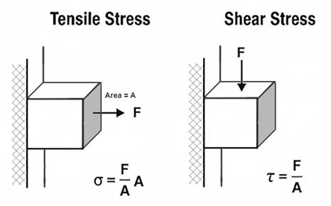
Shear stress is the sideways cousin – one part of a bolt sliding past the other, as when a hanger tries to cut it in half, to cut (shear) the bolt across its cross-section.
Ultimate stress (ultimate strength) is the max before breakage. Yield stress (yield strength) is the point where a bolt stops bouncing back and bends or stretches permanently. For metals, engineers define yield strength as 0.2% permanent deformation. Ratios of yield-to-ultimate vary wildly between alloys, which matters in picking metals. Note here that “strength” refers to an amount in pounds (or newtons) when applied to a part like a bolt but to an amount in pounds per square inch (or pascals) when applied to the material the part is made from.
Bolts in Theory, Bolts in Caves
The strength of wedge anchor made of 304 stainless depends on 304’s ultimate tensile strength (UTS) and the effective stress area of the bolt’s threaded region. Standard numbers: UTS ≈ 515 MPa (75,000 psi). For an M8 coarse bolt, tensile area = 36.6 mm². For a 3/8-16 UNC, it’s 50 mm².
As detailed elsewhere, a properly installed (properly torqued) bolt is not loaded in shear, regardless of the bolt orientation (vertical or horizontal) or the load application direction (any combination of vertical or sideways). But most bolts installed in caves are not properly installed. So we’ll assume that vertical bolts are properly torqued (otherwise they would fall out) and that horizontal bolts are untorqued. In such cases, horizontal bolts are in fact loaded in shear; the hanger bears directly on the bolt.
We can first look at the tension case – a wedge anchor in the ceiling; you hang from it. The axial (tensile) strength is calculated as UTS × A. This formula falls out of the definition of tensile stress: σ = F / A_t, where F is the axial force and A_t is the effective area over which the tensile stress acts. Shear stress (conventionally denoted τ where tensile stress is denoted σ) is defined as τ = F / A_s, where A_s is the area over which the shear stress acts.
In a bolt, A_t and A_s would seem to be identical. In fact, they are slightly different because the shear plane often passes through the threaded section at a slight angle from the tensile plane, thereby reducing the effective area. More importantly, ductile materials like 304 stainless steel undergo plastic deformation at the microscopic scale in a way that renders the basic theoretical formula (τ = F / A_s) less applicable. In this situation, the von Mises yield criterion (aka distortion energy theory) is typically used to predict failure under combined stresses. This criterion relates shear ultimate strength to tensile yield strength. The maximum shear stress a material can withstand (τ_max) is approximately equal to σ_yield / √3 × σ_yield. For predicting ultimate shear strength (USS), theory and empirical test data show that bolts made of ductile metals like mild carbon steel or 304 stainless have ultimate shear strength that is about 0.6 × their ultimate tensile strength.
The tensile stress area (A_s) for an M8 coarse thread bolt is 36.6 mm² (0.057 in²). For a 3/8-16 UNC bolt, A_s is 50 mm² (0.078 in²).
Simple math says:
| Diameter | Tensile Stress Area | Axial Strength | Shear Strength |
| M8 | 36.6 mm² | 4,236 lb | 2,542 lb |
| 3/8 inch | 50 mm² | 5,798 lb | 3,479 lb |
The 3/8 inch bolt has 37% higher tensile and shear strength than the M8 bolt, due to its larger effective cross-section. These values are ultimate strengths of the bolts themselves. Actual load capacities (strengths) of the anchor placement might be lower – if a hanger breaks, if the rock breaks (a cone of rock pulls away), or if the bolt pulls out (the rock yields where the bolt’s collar presses into it).
For reasons cited above (von Mises etc.), the shear strength of each bolt size is less than its tensile strength. For the 8mm bolt, is 2500 pounds (11 kn) strong enough? That’s about a factor of 14 greater than the weight of a 180 pound (80 kg) caver. That’s 14 Gs, which is about the maximum force that humans survive in harnesses designed to prevent a person’s back from bending backward – lumbar hyperextension. Caving harnesses, because of the constraints of single rope technique (SRT), do not supply this sort of back protection. Five to eight Gs is often cited as a likely maximum for survivability in a caving harness.
So 2500 pounds of shear strength seems strong enough, though possibly not super strong enough, whatever that might mean. Is the ratio of bolt strength to working load big enough? The ratio of survivable load to bolt strength? How might a person expecting to experience only the force of his body weight suddenly experience 5Gs?
The UIAA (International Climbing and Mountaineering Federation) sets a maximum allowable impact force for ropes at 12 kN (2700 lb) for a single rope, which means roughly 6-9 Gs for an average climber (75 kg, 165 lb.)
When a bolt is preloaded (tightened to a specified torque, often approaching its yield strength), it induces a compressive force in the clamped materials (the hanger, washer, and the rock) and a tensile stress of equal magnitude in the bolt. For a preloaded bolt, an externally applied load does not increase the tensile stress in the bolt until the external load approaches the preload force. This is because the external load first reduces the compressive force in the clamped materials rather than adding to the bolt’s tension. This behavior is well-documented in bolted joint mechanics (e.g., Shigley’s Mechanical Engineering Design).
For loads perpendicular to the bolt axis, preload can significantly enhance the bolted joint’s shear capacity. The improvement comes from the frictional resistance generated between the clamped surfaces (e.g., the hanger and concrete) due to the preload-induced compressive force. This friction can resist shear loads before the bolt itself is subjected to shear stress.
Basing preload on the yield strength of the bolts’ 304 stainless material (215 MPa, 31,200 psi) and the cross-sectional area of the threads used above gives the following preload forces:
M8 bolt preload: 215 MPa × 36.6 mm² ≈ 7,869 N (1,767 lb).
3/8 inch bolt preload: 215 MPa × 50 mm² ≈ 10,750 N (2,413 lb).
If we assume a coefficient of friction of 0.4 between hanger and bedrock, we can calculate the frictional forces perpendicular to horizontally placed bolts. These frictional forces can fully resist perpendicular (vertical) loads up to a limit of μ × preload (where μ is the friction coefficient and F_friction = μ × F_preload). For μ = 0.4, the shear resistance from friction alone could be:
M8: 0.4 × 7,869 N ≈ 3,148 N (707 lb).
3/8 inch: 0.4 × 10,750 N ≈ 4,300 N (966 lb).
These frictional capacities are substantial, meaning the bolt’s shear strength becomes relevant only if the frictional capacity is exceeded. The preload is highly desirable, because it prevents the rock and the bolt from “feeling” the applied load, and therefore prevents any cyclic loading of the bolt, even when cyclic loads are applied to the joint (via the hanger).
However, the frictional capacity (707 lb for M8) usually does not add to the shear capacity of the bolt, once preload is exceeded. Its shear capacity remains at 2542 lb as calculated above, because once the hanger slips relative to the rock, the bolt itself begins to bear the shear load directly.
Now, with properly torqued, preloaded bolts, we can return to the main question: are M8 bolts “good enough”? Two categories of usage come to mind – aid climbing and permanent rigging. Let’s examine each, being slightly conservative. For example, we’ll assume no traction or embedding of the hanger, something that often but not always exists, which results in an effective coefficient of friction between rock and hanger of 1.0 or more. We’ll use 8Gs as a threshold of survivability and 0.4 as a coefficient of friction – though friction becomes mostly irrelevant in this worst-case analysis.
Comparative Analysis – 3/8 vs M8 (first order approximations)
For an M8 bolt, preload near yield (215 MPa × 36.6 mm² = 7.9 kN / 1,767 lb) gives a frictional capacity of 0.4 × 7.9 kN = 3.16 kN (707 lb).
For a 3/8 inch bolt (215 MPa × 50 mm² = 10.8 kN / 2,413 lb), it’s 0.4 × 10.8 kN = 4.3 kN (966 lb).
The 8 G threshold (80 kg climber, 8 × 785 N = 6.3 kN / 1,412 lb) exceeds both frictional capacities, meaning the joint slips, and the bolt bears shear stress in these high-load cases, regardless of torquing.
Once friction is exceeded, the bolt’s shear strength governs: 11.3 kN (2,542 lb) for 8mm, 15.5 kN (3,479 lb) for 3/8 inch (based on 0.6 × UTS = 309 MPa).
Both M8 and 3/8 exceed 6.3 kN, confirming that the analysis hinges on shear strength, not friction, for high-load cases. Torquing is critical to achieve the assumed preload (near yield) and to confirm placement quality (a torqued bolt indicates a successful installation). However, in high-load cases (≥6.3 kN), the frictional capacity is irrelevant once exceeded, and the analysis stands on the bolt’s shear strength and the rock integrity.
Since high-load cases (e.g., 8 G = 6.3 kN) exceed the frictional capacity of both bolt diameters (3.16 kN for 8mm, 4.3 kN for 3/8 inch), the decision rests on shear strength margin:
M8: 11.3 kN (2,542 lb) provides a ~1.8x factor of safety (see note at bottom on factors of safety) over 6.3 kN.
3/8 inch: 15.5 kN (3,479 lb) offers a ~2.5x factor, ~37% higher, giving more buffer against rock variability or slight overloads.
In some limestone (10–100 MPa), the rock will fail (e.g., pullout) well below the bolt’s shear strength. Remember that with torqued bolts the rock does not “feel” any load until the axial load exceeds preload or the perpendicular load exceeds the friction force generated by the preload. But in softer (low compressive strength) limestone, once those thresholds are exceeded, the rock often fails before the bolt fails in shear or tension. 3/8 inch’s larger diameter distributes load better, reducing rock stress (bearing stress = force / diameter × embedment).
Most of us use redundant anchors for permanent rigging, and you should too. A dual-anchor system with partial equalization (double figure eight, bunny-loop-knot, 1–3 inch drop limit) ensures no single failure is catastrophic. A 3-inch drop would add ~1 kN to the force felt by the surviving anchor. This is within the backup bolt’s shear capacity, making 8mm viable.
What about practical factors? M8 bolts save ~20–35% battery life and weight, critical for remote locations. M8 does not align with ASC/UIAA standards (≥3/8 inch preferred). 3/8 is obviously better for permanent anchors in marginal rock, not because the bolt is stronger, but because the contact stresses are about 35% lower – a potentially significant difference.
Effect of Bolt Length on Anchor Failure in Limestone
In typical installations of wedge bolts in limestone, axial (tensile) loading, steel failure often governs (e.g., the bolt fractures at the threads), while in shear loading, the anchor typically experiences partial pullout with bending, followed by a cone-shaped rock breakout (pry-out failure). This is consistent with industrial experience in concrete, where tensile failures are steel-dominated due to the anchor’s expansion mechanism providing sufficient grip, but shear failures involve pry-out because the load induces bending and leverages the embedment. The collar (sleeve, expansion clip) in most brands is identical for all bolt lengths of a given diameter. The gripping mechanism doesn’t change with length. The primary difference is the effective embedment depth (h_ef), which affects load distribution in the rock. Longer bolts increase the volume of rock engaged and better resistance to breakout, but this benefit is more pronounced in shear than tension, as preload clamping compresses a larger rock section under the hanger, distributing stresses and reducing localized crushing.
To estimate failure loads for 2.5 inch vs. 3.5 inch total lengths, we can use standard engineering formulas adapted from ACI 318* (* I won’t violate copyright by linking to outlaw PDFs, but I think standards bodies that sell specs for hundreds of dollars do the world a huge injustice) for post-installed wedge anchors, treating limestone as analogous to concrete, with adjustments for its variable strength.
The compressive strength of limestone (f_c’) varies from 1,000 psi (soft, e.g., oolitic limestone) to 10,000 psi (harder types). We’ll use 4,000 psi (27.6 MPa) based on typical Appalachian limestone values. For stronger (compressive strength) limestone (e.g., 8,000 psi / 55 MPa), capacities increase by1.4x (proportional to the square root of f_c’).
Embedment Depth (h_ef) is the bolt length minus hanger thickness (~0.25 inch) and nut/washer (~0.375 inch). Thus, h_ef ≈ 1.875 inches for 2.5 inch bolt; h_ef ≈ 2.875 inches for 3.5 inch bolt. This assumes that a “good” hole has been drilled, allowing the collar to catch immediately as the bolt is torqued.
We’ll assume 304 stainless, ultimate tensile ~5,798 lb (25.8 kN), ultimate shear ~3,479 lb (15.5 kN), as previously calculated. 316 alloy would give similar results. We’ll assume proper torquing for preload and no edge effects, meaning the bolt is at least 10 bolt-diameters from edges and cracks.
Formulas (ACI-based, ultimate loads):
- Tensile Rock Breakout: N_cb ≈ 17 × √f_c’ × h_ef^{1.5} lb (k_c=17 for post-installed in cracked conditions; use for conservatism; f_c’ in psi, h_ef in inches).
- Axial Failure Load: Min(N_cb, steel tensile).
- Shear Pry-Out: V_cp ≈ k_cp × N_cb (k_cp=1 for h_ef < 2.5 inches; k_cp=2 for h_ef ≥ 2.5 inches, reflecting increased resistance to rotation).
- Shear Failure Load: Min(V_cp, steel shear), but with bending preceding rock failure.
- Capacities are ultimate (failure); apply safety factors (e.g., 4:1 per UIAA) for working loads.
With these formulas we can compare different bolt lengths in axial loading. Longer bolts increase h_ef, enlarging the breakout cone and distributing tensile stresses over greater rock volume. Preload clamping compresses the rock under the hanger (area ~0.5-1 in² depending on washer diameter), and longer bolts may slightly reduce localized stress concentrations at the surface due to better load transfer deeper in the hole. If rock breakout capacity exceeds steel strength, the bolt fractures. In weaker limestone, rock governs; in harder, steel does. The identical sleeve means expansion grip is consistent, so length primarily affects rock engagement.
So for 4000 psi limestone and 3/8 bolts in tension, axially loaded, we get:
2.5 inch (h_ef ≈ 1.875 in): N_cb ≈ 17 × 63.25 × (1.875)^{1.5} ≈ 2,765 lb (12.3 kN). Rock breakout governs (cone failure).
3.5 inch (h_ef ≈ 2.875 in): N_cb ≈ 17 × 63.25 × (2.875)^{1.5} ≈ 5,240 lb (23.3 kN). Rock breakout governs (cone-pullout).
For M8 bolts, axially loaded (2.5 in. ≈ 64mm, 3.5 in ≈ 90mm):
2.5 inch (h_ef ≈ 1.875 in): N_cb ≈ 17 × √4,000 × (1.875)^{1.5} ≈ 17 × 63.25 × 2.576 ≈ 2,765 lb (12.3 kN). Steel tensile = 4,236 lb (18.8 kN). Rock breakout governs (cone failure).
3.5 inch (h_ef ≈ 2.875 in): N_cb ≈ 17 × 63.25 × (2.875)^{1.5} ≈ 17 × 63.25 × 4.873 ≈ 5,240 lb (23.3 kN). Steel tensile = 4,236 lb (18.8 kN). Steel fracture governs (bolt breaks at threads, matching test observations).
2,765 lb (for both 3/8 and M8 bolts), particularly in redundant anchors, seems reasonable, based on the limits of human survivability and on the other gear in the chain. Nevertheless, this result surprised me. One-inch greater length doubles the effective anchor strength for axial loads.
When a shear load is large enough to exceed bolt preload (which should never happen with actual working loads), the shear force induces bending (lever arm from hanger to expansion point) and pry-out, where the bolt rotates, pulling out the back side and causing a cone breakout. Longer bolts increase h_ef, enhancing pry-out resistance by engaging more rock mass and distributing compressive stresses. If pry-out exceeds steel shear capacity, the bolt bends and shears. Industrial studies show embedment beyond 10x diameter (3.75 inches for 3/8 inch, 80mm for M8 bolts) adds minimal shear benefit.
For 4,000 psi limestone and 3/8 bolts with tensile loads:
2.5 inch (h_ef ≈ 1.875 in < 2.5 in): V_cp ≈ 1 × 2,765 lb ≈ 2,765 lb (12.3 kN). Rock pry-out governs (partial pullout, bending, then cone breakout).
3.5 inch (h_ef ≈ 2.875 in > 2.5 in): V_cp ≈ 2 × 5,240 lb ≈ 10,480 lb (46.6 kN) > steel shear → Steel governs (~3,479 lb [15.5 kN], with bending preceding shear failure).
For stronger limestone (8,000 psi compressive), 3/8 bolt capacities are ~1.4x higher (e.g., 3,870 lb for 2.5 in pry-out; steel 3,479 lb for 3.5 in), emphasizing length’s role in shifting from rock to steel failure.
For 4,000 psi limestone and M8 bolts with shear loads:
2.5 inch (h_ef ≈ 1.875 in < 2.5 in): V_cp ≈ 1 × 2,765 lb ≈ 2,765 lb (12.3 kN). Steel shear = 2,542 lb (11.3 kN). Steel shear governs (barely – bolt bends, then shears, with partial pullout).
3.5 inch (h_ef ≈ 2.875 in > 2.5 in): V_cp ≈ 2 × 5,240 lb ≈ 10,480 lb (46.6 kN). Steel shear = 2,542 lb (11.3 kN). Steel shear governs (bolt bends/shears before rock pry-out).
For harder limestone (8,000 psi), M8/8 bolt capacities are ~1.4x higher, again emphasizing length’s role in shifting from rock to steel failure.
2.5 inch: V_cp ≈ 1 × 3,870 lb ≈ 3,870 lb (17.2 kN). Steel = 2,542 lb. Steel shear governs.
3.5 inch: V_cp ≈ 2 × 7,340 lb ≈ 14,680 lb (65.3 kN). Steel = 2,542 lb. Steel shear governs.
Summary – Failure Loads in 1,000, 4,000, and 8,000 psi Limestone
([S] indicates steel failure, [R] indicates rock failure. Loads given in pounds and (kilonewtons):
| Bolt Size | 2.5 in Axial | 2.5 in Shear | 3.5 in Axial | 3.5 in Shear |
| 1000 psi limestone | ||||
| M8 (8mm) | 1,382 (6.15) [R] | 1,382 (6.15) [R] | 2,620 (11.7) [R] | 2,542 (11.3) [S] |
| 3/8 inch | 1,382 (6.15) [R] | 1,382 (6.15) [R] | 2,620 (11.7) [R] | 2,620 (11.7) [R] |
| 4000 psi limestone | ||||
| M8 (8mm) | 2,765 (12.3) [R] | 2,542 (11.3) [S] | 4,236 (18.8) [S] | 2,542 (11.3) [S] |
| 3/8 inch | 2,765 (12.3) [R] | 2,765 (12.3) [R] | 5,240 (23.3) [R] | 3,479 (15.5) [S] |
| 8000 psi limestone | ||||
| M8 (8mm) | 3,870 (17.2) [R] | 2,542 (11.3) [S] | 4,236 (18.8) [S] | 2,542 (11.3) [S] |
| 3/8 inch | 3,870 (17.2) [R] | 3,870 (17.2) [R] | 5,798 (25.8) [S] | 3,479 (15.5) [S] |
Bottom Line
For me, the key insight is that shear pry-out capacity in limestone anchors scales significantly with embedment depth. Extending bolt length from 2.5 to 3.5 inches increases pry-out resistance by approximately 100–200%, driven by the deeper rock engagement and the ACI 318 k_cp factor (1 for h_ef < 2.5 inches, 2 for h_ef ≥ 2.5 inches), though it’s ultimately capped by the bolt’s steel shear strength (2,542 lb / 11.3 kN for 8mm, 3,479 lb / 15.5 kN for 3/8 inch). When rock strength governs failure, as it often does in weaker (compressive strength) limestone (e.g., 1,000–4,000 psi), 3/8 inch bolts offer no advantage over 8mm (M8), as both have identical rock-limited capacities (e.g., 1,382 lb in 1,000 psi, 2,765 lb in 4,000 psi at 2.5 inches). Thus, choosing a 3.5 inch bolt over a 2.5 inch bolt is typically more critical than choosing between 3/8 inch and 8mm diameters.
Most bolts, particularly wall anchors in aid climbing or permanent setups, experience perpendicular loads. These are initially resisted by friction from tensile preload (e.g., 707 lb for 8mm, 966 lb for 3/8 inch with μ = 0.4), but when loads exceed this – as in a severe 8 G fall (1,412 lb / 6.3 kN for an 80 kg climber) – shear stress initiates. In caves I visit, permanent anchors are redundant, using dual bolts with crude equalization to limit drops to 1–3 inches, ensuring no single failure is catastrophic. In aid climbing, dynamic belays and climbing methodology/technique reduce criticality of single bolt failures. While 3/8 inch bolts provide ~37% higher steel strength (e.g., 3,479 lb vs. 2,542 lb shear), this margin is not a significant safety improvement in an engineering analysis, given typical climber weights (80–100 kg) and redundant anchor systems. Few people use stainless for aid climbs, but the numbers above still roughly apply for mild-steel bolts. In weak limestone (1,000 psi), rock failure governs at low capacities (e.g., 1,382 lb), making length critical and diameter secondary. In harder limestone (8,000 psi), 3/8 inch offers a slight edge, but redundancy and proper placement outweigh diameter differences. For engineering analysis, you can substitute 5/16 inch bolts for M8 in the above; just don’t mix components from each.
25-28 ft-lb seems a good torque for preloading 3/8-16 304 bolts and is consistent with manufacturers’ dry-torque recommendations. For 8mm and 5/16-18 304 bolts, manufacturers’ recommendations range from 11 (Fastenal, Engineer’s Edge, Bolt Depot) to 18 ft-lb (Allied Bolt Inc). For 304 SS (yield ~32 ksi), the tensile stress area of a 5/16-18 bolt is ~0.0524 in², so yield preload is about 1650 pounds. Most manufacturers seem a bit conservative on torque recommendations, likely because construction workers sometimes tend to overtorque. Using T = K × D × P (K ~0.2–0.35 dry for SS, D = 0.3125 in), 11 ft-lb, we get ~1,000–1,900 lb preload (below yield), while 18 ft-lb corresponds to ~1,700–3,100 lb. of preload. The latter is above yield for standard 304 stainless; Allied Bolt’s hardware appears to be a high-yield variant (ASTM F593-24) of 304. 304 can be cold-worked to achieve yield strengths above 70,000 psi. I’m using 32,000 psi for these calculations, so I’ll aim for 11-12 ft-lb of torque underground.
“Factor of Safety” Is a Crutch
We throw around “factor of safety.” It’s a crude ratio of strength to expected load. For example, M8 shear = 11.3 kN vs. 6.3 kN load → 1.8x. But that’s a false comfort. Real engineering moved past simple safety factors decades ago. Load and resistance factors, environment, materials, inspection – all matter more.
In the era of steam trains, designers would calculate the required cross section of a bolt based on design loads, and then “slap on a 3X” (factor of safety) and be done with it. The world then moved to limit-state design, damage tolerance, environment-specific factors, inspection and maintenance schedules, and probabilistic risk assessment. As a design philosophy, factor of safety is dead. As a bureaucratic metric for certification, even sometimes in aerospace, it persists.
The factor of safety, expressed as a ratio (e.g., 1.8 for an 8mm bolt’s shear strength of 11.3 kN over a 6.3 kN load), implies a simple buffer against failure. This can foster a false sense of security among non-technical users, suggesting that a bolt is “safe” as long as the ratio is greater than 1 (or pick a number). In reality, the concept oversimplifies the complexities of anchor performance in real-world conditions.
Factor of safety tends to roll up all sorts of unrelated ways that a piece of equipment or its placement might, in practice, not live up to its theory. It groups all the ways a part might degrade in use together – and groups all the ways any part in your hand might differ from the one(s) that got tested. In short, it is an overly sloppy concept that plays little part in the design of serious gear. Some parts don’t wear. Some manufacturing processes render every specimen of equal size, strength, and surface finish to a fraction of a percent. Some materials corrode like hell. Environments matter. Limestone compressive strength can range from 1 to 100 MPa in the same geologic formation. A poor placement with no preload can leave a 3 inch bolt that can be pulled out when the climber leaned back on it. Not an exaggeration; I have seen this happen – and saw the belayer, Andrea Futrell, go skidding six feet across the floor as a result. Never raised her voice. Dynamic belay par excellence.
Overemphasizing factor of safety can lead to dangerous assumptions, such as trusting a single anchor without redundancy, regardless of its size (do we really need more half inch bolts rusting away atop big drops), or neglecting regular gear inspection. For bolt placement, prudence and sanity insist that no single failure can be catastrophic. As is apparent from the above, proper torquing of bolts removes a great deal of unknowns from the equation.
I stress that “factor of safety” is a crude talking point that often reveals a poor understanding of engineering. So let’s be clear: survivable caving isn’t about safety factors. It’s about redundancy, placement, inspection, and understanding your rock.
That’s how you prevent overconfidence – and make informed decisions about stuff that will kill you if you screw up.
Six Days to Failure? A Case Study in Cave Bolt Fatigue
Posted by Bill Storage in Engineering & Applied Physics on July 17, 2025
The terms fatigue failure and stress-corrosion cracking get tossed around in climbing and caving circles, often in ways that would make an engineer or metallurgist cringe. This is an investigation of a bolt failure in a cave that really was fatigue.
In October, we built a sort of gate to keep large stream debris from jamming the entrance to West Virginia’s Chestnut Ridge Cave. After placing 35 bolts – 3/8 by 3.5-inch, 304 stainless – we ran out. We then placed ten Confast zinc-plated mild steel wedge anchors of the same size. All nuts were torqued to between 20 and 30 foot-pounds.
The gate itself consisted of vertical chains from floor to ceiling, with several horizontal strands. Three layers of 4×4-inch goat panel were mounted upstream of the chains and secured using a mix of 304 stainless quick links and 316 stainless carabiners.
No one visited the entrance from November to July. When I returned in early July and peeled back layers of matted leaves, it was clear the gate had failed. One of the non-stainless bolts had fractured. Another had pulled out about half an inch and was bent nearly 20 degrees. Two other nuts had loosened and were missing. At least four quick links had opened enough to release chain or goat panel rods. Even pairs of carabiners with opposed gates had both opened, freeing whatever they’d been holding.
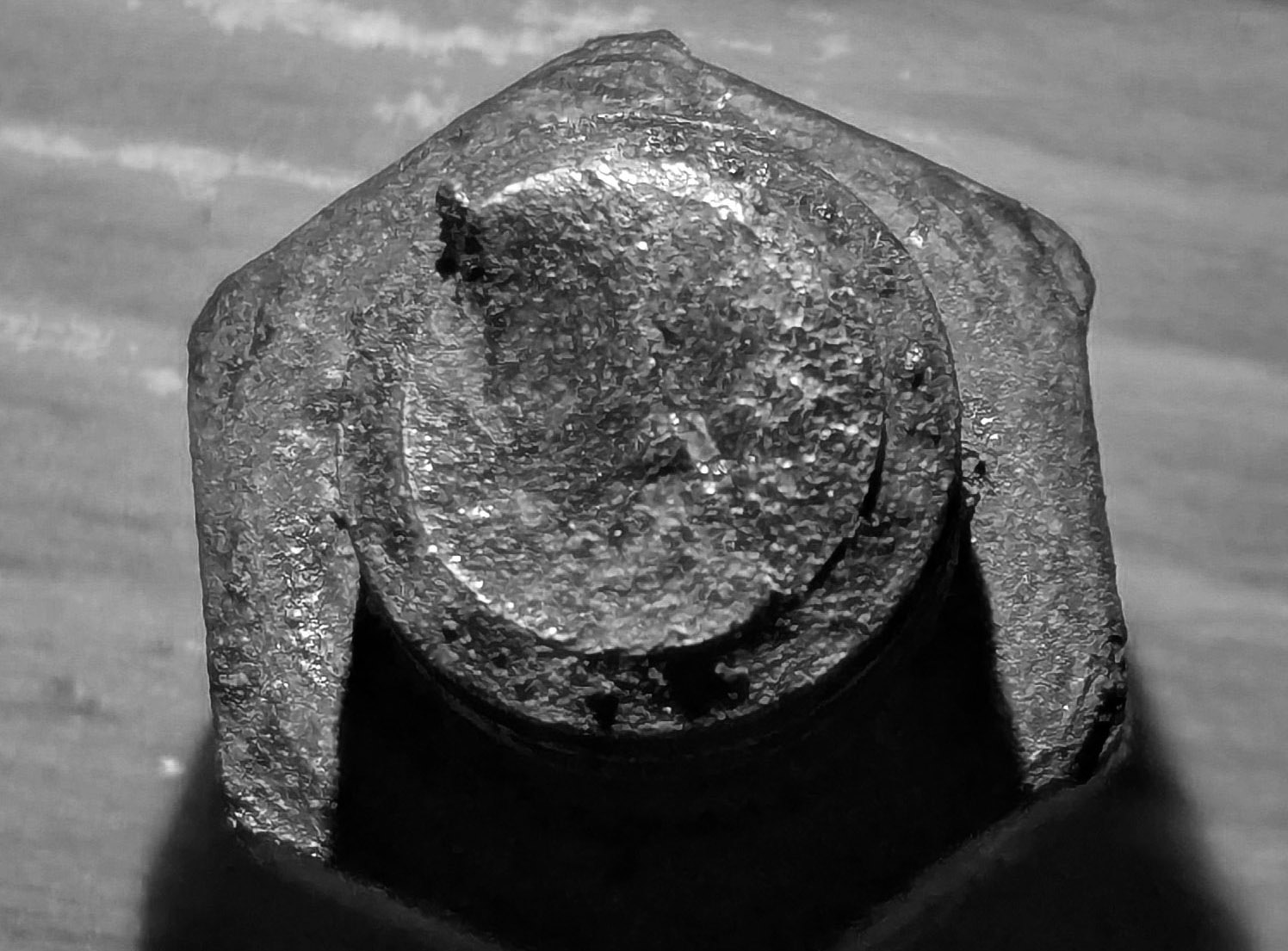
I recovered the hanger-end of the broken bolt and was surprised to see a fracture surface nearly perpendicular to the bolt’s axis, clearly not a shear break. The plane was flat and relatively smooth, with no sign of necking or the cup-and-cone profile typical of ductile tensile failure. Under magnification, the surface showed slight bumpiness, indicating the smoothness didn’t come from rubbing against the embedded remnant of the bolt. These features rule out a classic shear failure from preload loss (e.g., a nut loosening from vibration) and also rule out simple tensile overload and ductile fracture.
That leaves two possibilities: brittle tensile fracture or fatigue failure under higher-than-expected cyclic tensile load. Brittle fracture seems highly unlikely. Two potential causes exist. One is hydrogen embrittlement, but that’s rare in the low-strength carbon steel used in these bolts. The zinc-plating process likely involved acid cleaning and electroplating, which can introduce hydrogen. But this type of mild steel (probably Grade 2) is far too soft to trap it. Only if the bolt had been severely cold-worked or improperly baked post-plating would embrittlement be plausible.
The second possibility is a gross manufacturing defect or overhardening. That also seems improbable. Confast is a reputable supplier producing these bolts in massive quantities. The manufacturing process is simple, and I found no recall notices or defect reports. Hardness tests on the broken bolt (HRB ~90) confirm proper manufacturing and further suggest embrittlement wasn’t a factor.
While the available hydraulic energy at the cave entrance would seem to be low, and the 8-month time to failure is short, tensile fatigue originating at a corrosion pit emerges as the only remaining option. Its viability is supported by the partially pulled-out and bent bolt, which was placed about a foot away.
The broken bolt remained flush with the hanger, and the fracture lies roughly one hanger thickness from the nut. While the nut hadn’t backed off significantly, it had loosened enough to lose all preload. This left the bolt vulnerable to cyclic tensile loading from the attached chain vibrating in flowing water and from impacts by logs or boulders.
A fatigue crack could have initiated at a corrosion pit. Classic stress-corrosion cracking is rare in low-strength steel, but zinc-plated bolts under tension in corrosive environments sometimes behave unpredictably. The stream entering the cave has a summer pH of 4.6 to 5.0, but during winter, acidic conditions likely intensified, driven by leaf litter decay and the oxidation of pyrites in upstream Mauch Chunk shales after last year’s drought. The bolt’s initial preload would have imposed tensile stresses at 60–80% of yield strength. In that environment, stress-corrosion cracking is at least plausible.
More likely, though, preload was lost early due to vibration, and corrosion initiated a pit where the zinc plating had failed. The crack appears to have originated at the thread root (bottom right in above photo) and propagated across about two-thirds of the cross-section before sudden fracture occurred at the remaining ligament (top left).
The tensile stress area for 3/8 x 16 bolt would be 0.0775 square inches. If 65% was removed by fatigue, the remaining area would be 0.0271 sq. in. Assuming the final overload occurred at a tensile stress of around 60 ksi (SAE J429 Grade 2 bolts), then the final rupture would have required a tensile load of about 1600 pounds, a plausible value for a single jolt from a moving log or sudden boulder impact, especially given the force multiplier effect of the gate geometry, discussed below.
In mild steel, fatigue cracks can propagate under stress ranges as low as 10 to 30 percent of ultimate tensile strength, given a high enough number of cycles. Based on published S–N curves for similar material, we can sketch a basic relationship between stress amplitude and cycles to failure in an idealized steel rod (see columns 1 and 2 below).
Real-world conditions, of course, require adjustments. Threaded regions act as stress risers. Standard references assign a stress concentration factor (Kₜ) of about 3 to 4 for threads, which effectively lowers the endurance limit by roughly 40 percent. That brings the endurance limit down to around 7.5 ksi.
Surface defects from zinc plating and additional concentration at corrosion pits likely reduce it by another 10 percent. Adjusted stress levels for each cycle range are shown in column 3.
Does this match what we saw at the cave gate? If we assume the chain and fencing vibrated at around 2 Hz during periods of strong flow – a reasonable estimate based on turbulence – we get about 172,000 cycles per day. Just six days of sustained high flow would yield over a million cycles, corresponding to a stress amplitude of roughly 7 ksi based on adjusted fatigue data.
Given the bolt’s original cross-sectional area of 0.0775 in², a 7 ksi stress would require a cyclic tensile load of about 540 pounds.
| Cycles to Failure | Stress amplitude (ksi) | Adjusted Stress |
| ~10³ | 40 ksi | 30 ksi |
| ~10⁴ | 30 ksi | 20 ksi |
| ~10⁵ | 20 ksi | 12 ksi |
| ~10⁶ | 15 ksi | 7 ksi |
| Endurance limit | 12 ksi | 5 ksi |
Could our gate setup impose 540-pound axial loads on ceiling bolts? Easily – and the geometry shows how. In load-bearing systems like the so-called “death triangle,” force multiplication depends on the angle between anchor points. This isn’t magic. It’s just static equilibrium: if an object is at rest, the vector sum of forces acting on it in every direction must be zero (as derived from Newton’s first two laws of mechanics).
In our case, if the chain between two vertically aligned bolts sags at a 20-degree angle, the axial force on each bolt is multiplied by about a factor of eight. That means a horizontal force of just 70 pounds – say, from a bouncing log – can produce an axial load (vertical load on the bolt) of 540 pounds.
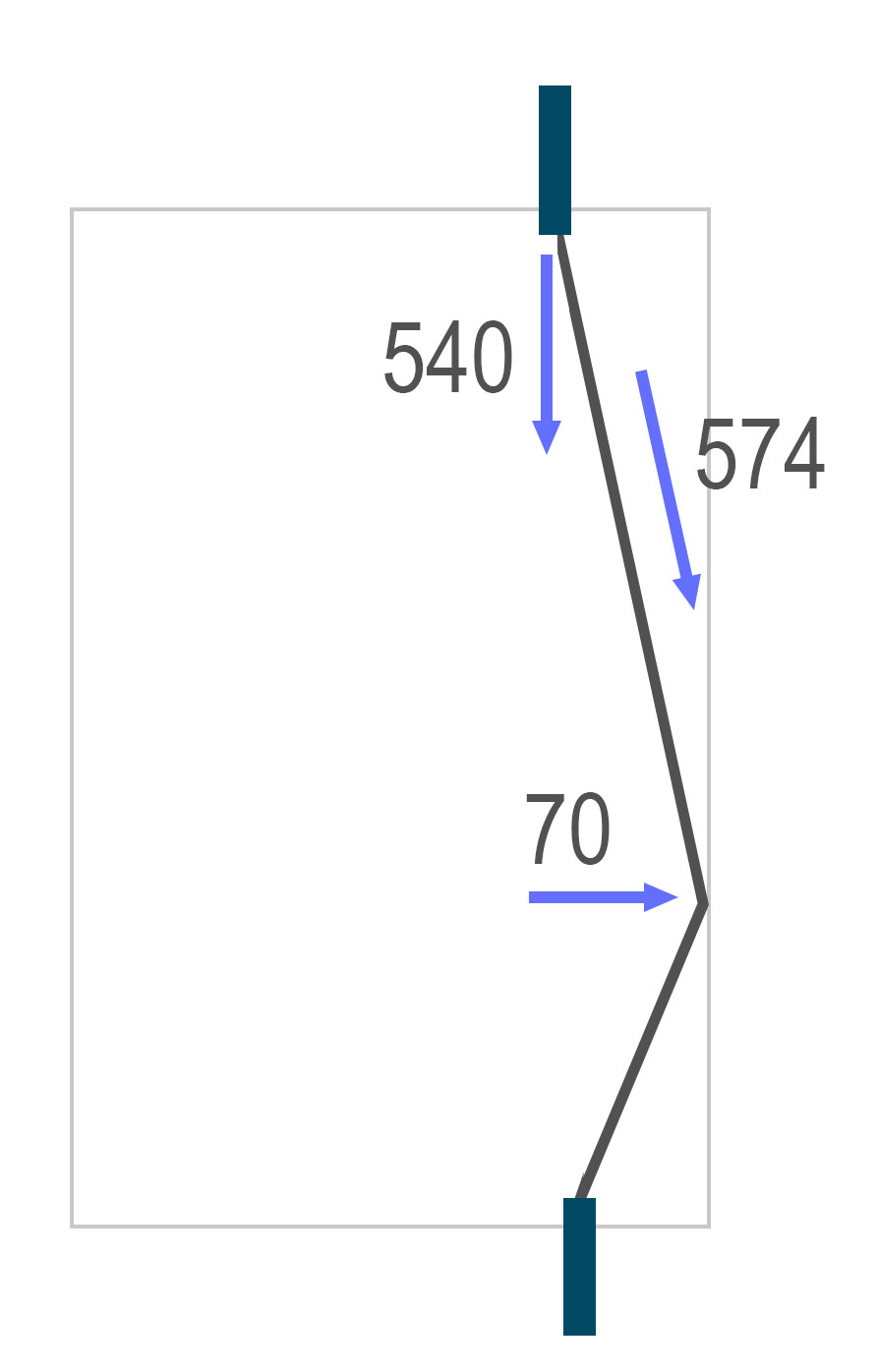
Under the conditions described above, six days of such cycling would be enough to trigger fatigue failure at one million cycles. If a 100-pound force was applied instead, the number of cycles to failure would drop to around 100,000.
The result was genuinely surprising. I knew the principles, but I hadn’t expected fatigue at such low stress levels and with so few cycles. Yet the evidence is clear. The nearby bolt that pulled partly out likely saw axial loads of over 1,100 pounds, enough to cause failure in just tens of thousands of cycles had the broken bolt been in its place. The final fracture area on the failed bolt suggests a sudden tensile load of around 1,600 pounds. These numbers confirm that the gate was experiencing higher axial forces on bolts than we’d anticipated.
The root cause was likely a corrosion pit, inevitable in this setting, and something stainless bolts (304 or 316) would have prevented, though stainless wouldn’t have stopped pullout. Loctite might help quick links resist opening under impact and vibration, though that’s unproven in this context. Chains, while easy to rig, amplified axial loads due to their geometry and flexibility. Stainless cable might vibrate less in water. Unfortunately, surface conditions at the entrance make a rigid or welded gate impractical. Stronger bolts – ½ or even ⅝ inch – torqued to 55 to 85 foot-pounds may be the only realistic improvement, though installation will be a challenge in that setting.
More broadly, this case illustrates how quickly nature punishes the use of non-stainless anchors underground.
Unlocking the Secrets of Bulk Metallic Glass with Graph Computing
Posted by Bill Storage in Engineering & Applied Physics on June 24, 2025
This blog post was written in May 2022 by Amy Skowronski and Bill Storage for {Company}. {Company} did not accept it (or a shorter version) for publication because it was tangential to their current (at that time) focus. I’ll comment on that decision in a future post.
Fraud detection, drug discovery, and network security have all advanced with the help of graph computing – but these are just the early, obvious wins. The deeper promise of {Company}’s graph-native platform lies in uncovering complex relationships in domains most systems aren’t built to touch. To show what that looks like, we turn to a frontier yet revealing application: a class of advanced materials known as Bulk Metallic Glass.
Imagine a metal that’s stronger than steel, bends like plastic, and resists corrosion like glass. Bulk metallic glass (BMG), discovered in the 1960s, was found to have such characteristics. Recent advancements, enabled in part by high performance computing, give this revolutionary material the potential to transform industries from aerospace to medical devices.
Unlike the orderly atomic structures of common metals, BMGs boast a chaotic, amorphous arrangement that defies traditional metallurgy. At {Company}, we’re harnessing the power of graph computing to decode BMG’s atomic secrets, unlocking new possibilities for materials science. In this post, we’ll explore how BMGs differ from common metals and why graph analytics is the key to designing the next generation of advanced materials.
What Makes Bulk Metallic Glass So Special?
To understand BMGs, let’s start with the basics of metal structure. Most metals like steel and aluminum form crystalline lattices. These are highly organized, repeating patterns of atoms. The lattices define how metals behave: their strength, ductility, and even how they corrode. Common arrangements include:
- Face-Centered Cubic (FCC): Picture a cube with atoms at each corner and in the center of each face. This is most aluminum and copper. FCC metals are more ductile, ideal for shaping into wires or sheets.
- Body-Centered Cubic (BCC): Think of a cube with an atom at each corner and one in the center (e.g., iron at room temperature, which becomes FCC at higher temperatures). BCC metals are strong but less ductile, making them prone to brittle fracture under stress.
- Hexagon Close-Packed (HCP): Imagine tightly packed spheres stacked in a hexagonal pattern. This is most magnesium and titanium. HCP metals offer a balance of strength and formability, common in aerospace components.
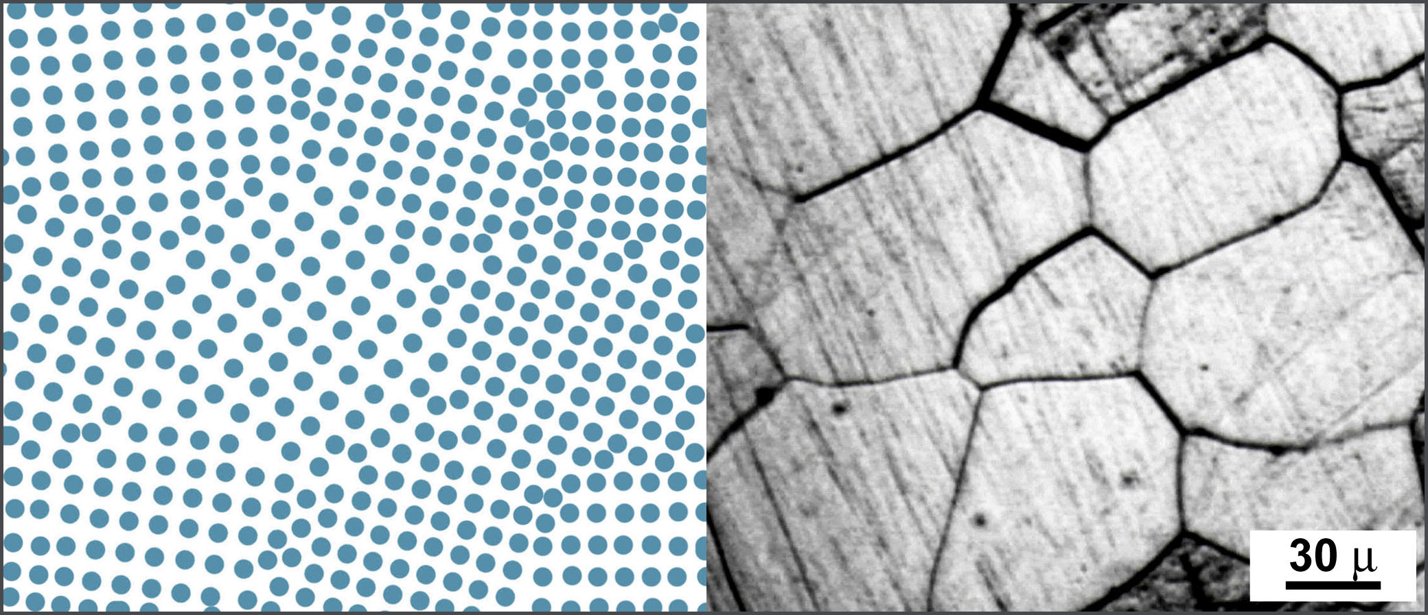
All these structures are orderly, predictable, and rigid. But they have flaws – dislocations and grain boundaries where crystal regions meet. The boundaries act like seams, weaker than the surrounding fabric. Cracks and corrosion exploit the boundaries. Enter bulk metallic glass.
BMGs are amorphous; their atoms are arranged in a random, glass-like state, resembling a frozen liquid. Instead of lattices, BMG atoms are arranged in tightly packed clusters. This chaos gives BMGs unique properties:
- Incredible Strength: Without grain boundaries, BMGs resist cracking. Their strengths reach 2–3 GPa (300,000–400,000 psi), exceeding that of many high-strength steels, which typically top out around 1.5–2 GPa.
- Elasticity: BMGs can flex like polymers, deforming up to 2% before yielding, far exceeding the behavior of normal metals.
- Corrosion Resistance: Absence of ordered planes makes it harder for chemicals to attack and penetrate. BMGs are ideal for harsh environments like jet engines or implants.
- Processability: BMGs can be molded like glass when heated into their supercooled liquid region, enabling complex shapes for gears or biomedical stents.
Of course, there’s a catch, one that has hindered BMG development for decades. Designing BMGs is arduous. Their properties depend on precise compositions (e.g., Zr41.2Ti13.8Cu12.5Ni10Be22.5, known as Vitreloy 1) and extreme cooling rates in early systems (10⁵–10⁶ K/sec), though modern BMGs can form at rates as low as 1–100 K/sec. Understanding their atomic structure means solving a 3D puzzle with billions of pieces.
Graph Computing: Decoding BMG’s Atomic Chaos
BMGs’ amorphous structure is a network of atoms connected by bonds, with no repeating pattern. This makes them a perfect fit for graph analytics, where atoms are nodes and bonds are edges. {Company’s} high-performance graph platform can model these atomic networks at massive scale, revealing insights that traditional tools can’t touch. Here’s how it works:
1. Modeling the Amorphous Network
Imagine a BMG sample with billions of atoms, each bonded to 8–13 neighbors in a random cluster. {Company} represents this as a graph. Each node (atom) has properties like element type (e.g., Zr, Cu) and position. Each edge (bond) has attributes like bond strength or distance. Unlike crystalline metals, where lattices repeat predictably, BMG graphs are irregular, with varying degrees (number of bonds per atom) and clustering coefficients (how tightly atoms pack locally).
Using {Company’s} distributed graph engine, researchers can ingest terabytes of molecular dynamics (MD) simulation data – snapshots of atomic positions from supercomputers – and build these graphs in real time. Our platform’s ability to handle sparse, irregular graphs at scale (think 109 nodes and 1010 edges) makes it ideal for BMGs, outperforming traditional methods by 10–100x.
2. Analyzing Local Atomic Clusters
BMGs owe their strength to short-range order – local clusters like icosahedra (12 atoms around a central one) or tetrahedra (4 atoms tightly packed). These clusters don’t repeat globally but dominate locally, influencing properties like ductility. {Company’s} graph algorithms, like community detection (e.g., Louvain clustering), identify these motifs by finding densely connected subgraphs. For example, a high icosahedral cluster count in a Zr-based BMG correlates with better glass-forming ability and higher resistance to shear localization.
We also use graph neural networks (GNNs) to predict cluster stability. GNNs, using high-quality training data, learn from the graph’s topology and node features (e.g., atomic radii, electronegativity), predicting which compositions favor amorphous structures. This accelerates BMG design, reducing trial-and-error in the lab.
3. Simulating Defects and Dynamics
BMGs aren’t perfect. Shear transformation zones (STZs) – regions where atoms rearrange under stress – control their plasticity. {Company} models STZs as anomalous subgraphs, where nodes have unusual connectivity (e.g., lower or higher degree than average). Our anomaly detection algorithms can pinpoint these defects, helping engineers predict failure points.
Dynamic processes, like atomic rearrangements during cooling, are modeled as temporal graphs, where atom positions and inferred bonds change over time due to thermal motion or stress. {Company’s} real-time processing (powered by HPC roots) tracks these changes at scale, revealing how cooling rates affect amorphous stability. This is critical for scaling BMG production, because slow cooling often leads to unwanted crystallization.
4. Optimizing Composition
BMG recipes are complex, with 3–5 elements in precise ratios. {Company’s} graph traversal algorithms explore compositional spaces, identifying combinations that maximize icosahedral clusters or minimize crystallization risk. For instance, adding 1% Be to a Zr-Cu alloy can stabilize the amorphous phase. Our platform integrates with machine learning pipelines, enabling researchers to iterate faster than ever.
Why BMG Matters to Industry
BMGs are already making waves:
- Aerospace: NASA’s BMG gears for Mars rovers (developed and tested, not production to our knowledge) are 2x stronger than titanium, with no grain boundaries to fail under stress.
- Medical Devices: BMG implants resist corrosion in the body, lasting longer than the best stainless steels.
- Electronics: BMG casings for smartphones (e.g., Apple’s trials) combine strength with moldability for sleek designs.
The Future of Materials Science with {Company}
The global advanced materials market is projected to hit $1.1 trillion by 2027, and BMGs are a growing slice. But their potential is untapped due to design complexity. {Company’s} graph platform bridges this gap, enabling researchers to model, analyze, and optimize BMG structures at unprecedented scale. {Company’s} graph computing platform, with its roots in high-performance computing and expertise in Graph AI, is the perfect partner for this journey.
Concrete Screws in Cave Exploration
Posted by Bill Storage in Engineering & Applied Physics on June 18, 2025
This hastily assembled piece expresses concerns over the use of concrete screws in caving. It stems from a discussion with Max Elfelt last night. Two aspects of screw use underground interact adversely: 1) screws rely on rock tensile strength while wedge bolts rely on compressive strength, and 2) the uncharacteristically large difference between tensile and compressive strength in cave-forming limestone, particularly oolitic types. Combined, they raise significant concerns. Comments are welcome, either below or privately. Find me in the NSS directory, on X, or LinkedIn.
Cave exploration demands absolute trust in permanent rigging for pits, climbs, and traverses where falls could be fatal. Anchors, the critical connection points securing ropes to cave walls, must withstand the forces of climbers, falls, and environmental wear. While concrete screws have gained attention in some climbing communities for their ease of installation, their use as permanent or semi-permanent rigging in caves and in any cases where axial loads (pullout forces along the anchor’s axis) are possible may pose unacceptable risks.
Unlike wedge bolts, which rely on the rock’s compressive strength to create a secure grip, concrete screws depend heavily on the rock’s tensile and shear strength, properties that appear, on the basis of reported mechanical properties, to be inadequate for safe use of screws in cave-forming limestones, particularly oolitic and anisotropic varieties (those having different properties in different directions, typically caused by depositional discontinuities – bedding planes – or cemented planar fractures). A quick look at the mechanical differences between these materials reveals grounds for concern – possibly grave concern.
The Mechanics of Anchors: Wedge Bolts vs. Concrete Screws
Wedge bolts work by inserting a bolt into a drilled hole, then tightening it (torquing the nut) to push a cone-shaped wedge against the sides of the drilled hole. This action generates a high clamping force called preload. Preload allows the bolt to resist axial loads without any further movement of the bolt in the hole when even large loads are applied to the hanger. The preload is verifiable during installation: if torque is felt by hand or measured with a wrench (27 Nm or 20 foot pounds for 10 mm or 3/8 inch anchors), the rock is compressing adequately, the needed friction has been generated, and the desired preload exists. The physics and mechanics of wedge bolts ensures that applied axial or perpendicular loads, if they are less than the amount of axial preload (several thousand pounds, or greater than 10KN), do not alter the stress states of the installed bolt or the adjacent rock at all. The mechanics of wedge bolts and how they are misunderstood by climbers appears in a paper by Amy Skowronski and me in the Oct 2024 Journal of Search and Rescue.
Concrete screws, in contrast, operate somewhat like screws in wood. However, this analogy has serious limitations, discussed below. Concrete screws are threaded directly into a pre-drilled hole, cutting or crushing threads into the rock. Unlike wedge bolts, preload is not a significant factor of the gripping mechanics. Their resistance to axial loads depends on the mechanical interlock between threads and rock. When a caver applies force – either axial or perpendicular loading – the threads bear against the rock, inducing shear stress as threads resist sliding. Applied axial loads, if present, induce tensile stress as the rock resists radial pulling apart. This makes the rock’s tensile and shear strengths critical, as failure at the thread-rock interface will result in pullout. Cyclic loading – each time a load is added and removed during descending, ascending, or falling – causes wear, micro-fractures, and grain dislodgement. This increases the induced stresses by reducing the size of the surfaces under shear and tensile stress. Use of concrete screws in climbing is discussed in The Bolting Bible, about which I express several concerns below.
Material Mechanical Properties: Concrete vs. Limestone
The suitability of bolts and screw anchors hinges critically on the rock’s mechanical properties. The limestone that forms most caves has highly variable strength, unlike concrete, which is engineered for consistency. More critically, the relationship between compressive strength and tensile strength is predictable in concrete, but less so in limestone. Below are comparisons of compressive and tensile strengths, focusing on cave-relevant limestones, particularly oolitic and anisotropic types.
| Property | Structural Concrete | Oolitic Limestone | Anisotropic Limestone |
|---|
| Compressive Strength | 20–200 MPa | 20–60 MPa (varies with porosity and cementation) | ~20–180 MPa (depending on bedding and orientation) |
| Tensile Strength (Direct) | 2–5 MPa | ~0.5–4 MPa | Highly variable: ~0.5–6 MPa depending on bedding details |
| Modulus of Rupture | 3–7 MPa | ~0.5–5 MPa | ~0.5–12 MPa |
| Anisotropy | Highly isotropic | Weakly anisotropic | Strongly anisotropic (bedding planes matter greatly) |
| Failure Mode in Tension | Brittle fracture | Grain-boundary separation | Splitting along bedding or delamination |
| Elastic Modulus (Young’s) | 25–50 GPa (typical NSC) | ~5–30 GPa | ~10–50 GPa, highly dependent on direction |
* Granite, for comparison, often has a compressive strength of 100–200 MPa and a tensile strength of ~7–20 MPa. Tensile strength measurements are from splitting (ASTM C496) and flexure (ASTM C78) tests. Low-tensile oolite strength values from Ippolito (1975), Szechy (1966), and Paronuzzi (2009).
Why Concrete Screws in Caves Might Be Riskier than We Think
The disparity between compressive and tensile strengths in limestone, particularly oolitic and anisotropic types, is large. Wedge bolts rely on limestone’s compressive strength (20 MPa or greater), which is sufficient to develop preload in typical cave limestones. The preload reduces reliance on the rock’s tensile/shear strength and eliminates cyclic wear concerns for expected loads.
Concrete screws depend on limestone’s tensile and shear strength, not its compressive strength) to resist axial loads. Stresses induced by cavers’ weight or falls (e.g., 5–15 kN, translating to 1–3 MPa at the thread interface, depending on thread geometry – see sample calculations at the bottom of this post) are dangerously close to (and possibly exceed in cases) the tensile strengths of the limestone in which they are placed. In some oolitic limestone, the weak matrix fails under thread stresses, causing grain dislodgement or micro-fractures, especially under cyclic loading, though specific performance data in cyclic loading in material like oolitic limestone is lacking. Unlike wedge bolts, where preload is confirmed at installation, concrete screws offer no such assurance, and their performance necessarily degrades over time because each each load application results in fretting fatigue. Common caving field-tests for limestone compressive strength (e.g., the ring of a hammer blow) are unlikely to reliably predict tensile strength, particularly when the tensile strength of the matrix is low compared to that of the grains (clasts), as is the case with many oolitic limestones.
This disparity arises because both hard and soft rocks can undergo brittle fracture and are prone to tensile failure under localized stresses, whereas they resist compression better, due to grain-to-grain contact even after the matrix yields. In oolitic limestone, the rock consists of hard, spherical grains (ooids) cemented by a softer matrix (e.g., calcite). The matrix’s tensile and shear strengths are significantly lower than the bulk compressive strength, which is dominated by the hard grains. When a concrete screw is installed, its threads cut or crush into the matrix, and under axial load, the matrix must resist shearing or tensile failure. If the matrix is weak (e.g., porous or amorphous cement), the threads can dislodge grains by fracturing the matrix, reducing pullout strength over time, especially under cyclic loading. Manufacturers like Simpson Strong-Tie (Titen HD screws) report pullout strengths of 42–52 kN in hard limestone and concrete, but these assume isotropic substrates, not cave limestones with weak matrices or bedding planes.
Another consideration gives rise to even greater concern regarding placement in oolitic limestones, particularly those with large ooids. ASTM C496 tensile strength tests seem likely to overestimate oolitic limestone’s tensile strength for predicting concrete screw pullout. Overestimation of tensile strength for the screw scenario is likely because of the large size of the test specimen (152 mm, 6 inches), the test’s bulk measurement (e.g., 2–5 MPa) versus the matrix’s lower tensile/shear strength (e.g., 1–3 MPa) and the size of ooids compared to that of the threads (1–2 mm threads and .25–1 mm ooids). The test’s homogenized results probably don’t capture localized matrix failure adjacent to threads.
Cause for Concern in the Common Caving Use Case
Our discussions with cavers who use concrete screws suggest that they are used only for aid climbs (temporary placement) and only where the nominal applied load is not axial, i.e., they use horizontal screws with vertical applied loads. This, in theory, would eliminate concerns about the low tensile strength of certain limestones. One part of the allure of concrete screws is that no hammer or wrench is needed for installation. If hammer, wrench, and wedge anchors aren’t available at the top of a climb, screws then take on a role slightly more critical than their use on the climb itself. Many scenarios at the top of climbs entail a descent setup where some degree of axial loading is inevitable. All descents entail some degree of cyclic loading. Similarly, a fall when the climber is above a single bolt (first bolt placed only) in a climb will always result in significant axial loading.
Five factors combine to raise considerable concern for these and similar scenarios.
- The unusual relationship between compressive and tensile strength of common limestones.
- The absence of evidence for how many load cycles are needed to cause significant tensile yielding of the internal threads carved by screws
- The small margin between tensile strength (ultimate tensile stress) of certain limestones and normal working loads in use
- The lack of confirmation of a successful screw installation such as the resistance to torquing with wedge bolts
- Inability to assess tensile strength of the limestone by a means such as listening to the sound of a hammer blow
Intuitions about strength properties of common materials may further exacerbate the situation. Metals’ tensile strength is typically 80 or 90 percent of its compressive strength. In limestone, this ratio is 10 to 15%. In oolitic and anisotropic limestone, it can be below 5 percent.
Finally, the prominence of analyses of climbing gear – gear used on the surface – consisting mainly of dramatic measurement of ultimate strength may work against us. Pull-tests, while entertaining, are not particularly useful in evaluating the utility of any mechanical component. Cavers may face increased risk by extending conclusions drawn from non-representative test scenarios common on YouTube, for example.
This concludes the thrust of my concern about concrete screws in caves. I welcome comments and corrections. Below are sections on calculating expected pullout loads of screws, discussion of fatigue and fretting fatigue, and specific concerns on the discussion of concrete screws in the Bolting Bible. These are engineering/physics oriented, and the above concerns hold independent of the topics below. Stop here if you’re not drawn math, physics, or nit picking.
The Bolting Bible
The Bolting Bible offers much useful instruction and information on bolts and screws used in climbing. The article/chapter “The Book of Concrete Screws” by HowNOT2 aims to educate climbers about concrete screws as temporary or sometimes permanent anchors in rock climbing. While it provides practical insights and test data, it has, in my opinion, several shortcomings in terms of physics and engineering rigor. That rigor seems to me something that should be present in coverage of a relatively new technique, especially when any discussion of permanent rigging is present. The Bolting Bible explicitly disclaims scientific rigor but its comprehensiveness is understood by many to imply authority.
The article describes concrete screws as functioning “similarly to normal wood screws” where “threads bite into the sides of the hole.” The analogy may aid visual intuition, but it risks conflating fundamentally different material behaviors – elastic-plastic deformation in wood versus brittle fracture and micro-spalling in rock. It fails to explain how the threads interact with the rock substrate, particularly the stress concentrations at the thread-rock interface.
The article mentions that concrete screws are “not safe in soft rock” and can “strip the threads” in hard rock, but it provides no quantitative or mechanical reasoning. Hard and soft don’t adequately cover the variations in mechanical properties of rock to orient readers toward meaningful distinctions in substrate performance.
The article briefly notes that cyclic loading in soft rock can cause concrete screws to “lose grip” due to threads dislodging material. “Losing grip” is a casual phrase that erases the actual failure modes involved: local pulverization of rock around threads, progressive thread shearing, and fretting fatigue under micro-motion (see discussion of fatigue at bottom). The language reduces complex, cumulative damage to a vague sensation.
The article cites break tests (e.g., Simpson Strong-Tie Titen HD screws achieving 42–52 kN [9400–11700 pounds] before head shear. The head-shear test is meaningless to climbing or caving use cases and might create a false sense of safety margin. While empirical data is valuable, the absence of a theoretical framework (e.g., thread shear strength, rock compressive strength) limits the generalizability of the findings and utility of the conclusions.
The suggestion to “spit or squirt water,” though possibly derived from field experience, should be followed by some observed benefit with even a speculative mechanism: Does moisture reduce dust, increase thread cutting efficiency, or initiate micro-hydration in porous substrates? Without this, it reads as lore rather than low-tech science.
As is the case with most gear analyses that measure ultimate strength, the article’s focus on ultimate strength (e.g., head shear at high loads) misses the more relevant issue for climbers: long-term reliability under repeated sub-failure loads, particularly given the key difference in mechanism between wedge bolts, with which most cavers are familiar, and concrete screws, which have come onto the scene fairly recently.
The article emphasizes ease of installation and removal for temporary anchors but does not adequately address the ethical implications of leaving potentially compromised holes in rock, especially in public climbing areas. Drilling holes is a “permanent deformation to the rock,” as noted elsewhere in The Bolting Bible, yet the article does not discuss how concrete screw holes might affect future bolting. “Bolt-farm” problems of the past might shift to hole-farm problems.
An assoicated HowNot2 video mentions permanent rigging using screws, stating that the screws should be stainless steel. Stainless eliminates the problem of screw deterioration from corrosion. This is a distraction from the more relevant concern of hole degradation. The video mentions that repeated use has led to “spinners” without noting that if a screw spins, the threads it carved into the rock are completely compromised. If a screw spins, unlike the case with a wedge bolt, it has no resistance to pullout.
Expected Pullout Load in Low-Tensile Oolitic Limestone
To calculate the effective contact area of a 3/8-inch diameter, 3-inch long concrete screw in tension, we must estimate the area over which the threads engage the concrete and can transfer tensile load. This is not the same as the root cross-sectional area of the screw (which governs tensile failure of the screw itself); you’re asking about the interface area between the screw threads and the concrete, which governs pullout or bond failure.
Nominal Parameters
- Screw outer diameter: 3/8 inch = 0.375 in
- Length embedded in concrete: 3 inches
(Assuming full 3-inch embedment and no voids) - Thread type: typical concrete screw (e.g., Tapcon) with a coarse thread (approx. 7–8 threads per inch)
Basic Bond Area (Cylindrical Surface)
This is a simplification that treats the bond area as a cylinder with the mean thread diameter:
Total contact area = π ⋅ mean diameter ⋅ embedded length where:
mean diameter = (outer diameter – root diameter) / 2
For a 3/8″ 3-inch Tapcon-style screw:
Outer diameter ≈ 0.375 in.
Root diameter ≈ 0.275 in.
Mean diameter ≈ (0.375 + 0.275)/2 = 0.325 in
Therefore, total contact area ≈ π ⋅ 0.325 ⋅ 3 ≈ 3.06 sqin.
Thread Engagement Area
Threads only contact the concrete at the flank surfaces, not over the full cylindrical shell. Accounting for thread flank angle and spacing typically reduces effective contact area to 40–60% of the full cylindrical surface, depending on thread profile.
Assuming 50% effective contact: Contact area = 1.5 sqin.
Tensile strength of weak but not weakest oolitic limestone = 1MPa = 145 psi. Note that reports on limestone tensile tests indicate that strengths lower than 1MPa could be encountered in oolitic and anisotropic limestones. West Virginia’s Pickaway Limestone comes to mind.
Expected pullout load in limestone having 1MPa (145 psi) tensile strength = 150 psi ⋅ 1.5 sqin = 225 pounds (or 112 pounds for 0.5 MPa tensile limestone)
Fatigue
The term fatigue, as used in engineering, has specific technical meanings that might differ from how it is used casually in discussing gear. The most general use describes gradual reduction in strength after many cycles (typically 10,000 to 1 million cycles) of stress application where the applied stress involves superficially elastic deformation (as opposed to plastic deformation in which measurable yielding of material occurs).
Low cycle fatigue in metals describes strength reduction from cyclic loading up to about 10,000 cycles where measurable plastic (doesn’t bounce back) deformation occurs.
Both high and low-cycle fatigue in metals happen when, at the microscopic level, even when the macroscopic stress is elastic, dislocations move within favorably oriented grains of the crystalline metal. 304 stainless steel typically has an ASTM grain size number of 5 to 10, corresponding to grain diameters of about 15 to 65 microns. Repeated dislocation during cyclic loading can form persistent slip bands, which are localized zones of plastic deformation that can eventually break through the surface. These act as initiation sites for fatigue cracks.
Localized plastic deformation around slip bands creates intrusions and extrusions on the surface. Over thousands to millions of cycles, these become tiny microcracks, usually less than a grain diameter long. Initially, crack growth follows crystallographic planes (especially {111} slip planes in body-centered cubic or face-centered cubic structures – for those who are into crystals). This is called Stage I (shear-mode) propagation.
Once a crack crosses a few grains, it becomes long enough to be governed by stress intensity rather than just local slip. The crack then grows perpendicular to the maximum principal stress (Stage II, or tensile-mode crack growth). When the crack becomes long enough that the remaining material cross-section can’t support the applied load, sudden ductile or brittle fracture occurs, depending on material properties (particularly its toughness) and loading rate.
From this description, you can see that fatigue is unlikely to be a failure mode in either wedge bolts or concrete screws as used in caves or in rock climbing (in contrast to what is stated in climbing literature here and here); the applied loads are too small and the number of cycles is too low.
Above I used the term fretting fatigue to describe rock wear along the threads carved into the rock by a concrete screw. I want to be careful in using a term possibly in a non-standard way. This is a very different use of the general term fatigue in mechanics. Here I refer to a form of fatigue failure that occurs when a component (rock in this case, not the screw) experiences both cyclic loading and simultaneous small-amplitude oscillatory motion (microslip) at the contact surface with another component (the screw). This microscale rubbing involves very high contact forces and greatly reduces component life – to a degree that the term fatigue does not apply like it does in the cyclic loading of metal. Fretting fatigue usually describes a condition found at bolted joints, riveted connections, spline shafts, blade roots, or where two components are clamped but subjected to vibration or relative motion.
Physics for Frisco motorheads
Posted by Bill Storage in Engineering & Applied Physics on July 28, 2019
San Francisco police are highly tolerant. A few are tolerant in the way giant sloths are tolerant. Most are tolerant because SF ties their hands from all but babysitting the homeless. Excellent at tolerating heroin use on Market Street, they’re also proficient at tolerating vehicular crime, from sailing through red lights (23 fatalities downtown last year) to minor stuff like illegal – oops, undocumented – car mods.
For a progressive burg, SF has a lot of muscle cars, Oddly, many of the car nuts in San Francisco use the term “Frisco,” against local norms.
Back in the ’70s, in my small Ohio town, the losers drove muscle cars to high school. A very few of these cars had amazing acceleration ability. A variant of ’65 Pontiac Catalina could do zero to 60 in 4 1/2 seconds. A Tesla might leave it in the dust, but that was something back then. While the Catalina’s handling was awful, it could admirably smoke the starting line. Unlike the Catalina, most muscle cars of the ’60s and ’70s – including the curvaceous ’75 Corvette – were total crap, even for accelerating. My witless schoolmates lacked any grasp of the simple physics that could explain how and why their cars were crap. I longed to leave those barbarians and move to someplace civilized. I ended up in San Francisco.
Those Ohio simpletons strutted their beaters’ ability to squeal tires from a dead stop. They did this often, in case any of us might forget just how fast their foot could pound the pedal. Wimpy crates couldn’t burn rubber like that. So their cars must be pretty badass, they thought. Their tires would squeal with the tenderest touch of the pedal. Awesome power, right?
Actually, it meant a badly unbalanced vehicle design combined with a gas-pedal-position vs. fuel-delivery curve yielding a nonlinear relationship between pedal position and throttle plate position. This abomination of engineering attracted 17-year-old bubbas cocksure that hot chicks dig the smell of burning rubber. See figure A.

Fig. A
This hypothetical, badly-designed car has a feeble but weighty 100 hp engine and rear-wheel drive. Its rear tires will squeal at the drop of a hat even though the car is gutless. Its center of gravity, where its weight would be if you concentrated all its weight into a point, is too far forward. Too little load on the rear wheels.
Friction, which allows you to accelerate, is proportional to the normal force, i.e. the force of the ground pushing up on the tires. That is, the traction capacity of a tire contacting the road is proportional to the weight on the tire. With a better distribution of weight, the torque resulting from the frictional force at the rear wheels would increase the normal force there, resulting in the tendency to do a wheelie. This car will never do a wheelie. It lacks the torque, even if the meathead driving it floors it before dumping the clutch.
Figure A is an exaggeration of what was going on in the heaps driven by my classmates.
Above, I noted that the traction capacity of a tire contacting the road is proportional to the weight on the tire. The constant of proportionality is called the coefficient of friction. From this we get F = uN, meaning frictional force equals the coefficient of friction (“u”) times the normal force, which is, roughly speaking, the weight pushing on the tire.
The maximum possible coefficient of friction on smooth surfaces is 1.0. That means a car’s maximum possible acceleration would be 1g: 32 feet per second per second. Calculating a 0-60 time based on 1g yields 2.73 seconds. Hot cars can momentarily exceed that acceleration, because tires sink into small depressions in pavement, like a pinion engaging a rack (round gear on a linear gear).
Here’s how Isaac Newton, who was into hot cars, viewed the 0-60-at-1-g problem:
- Acceleration is change in speed over time. a = dv/t.
- Acceleration due to gravity (body falling in a vacuum) is 32.2 feet per second.
- 5280 feet in a mile. 60 seconds in a minute.
- 60 mph = 5280/60 ft/sec = 88 ft/sec .
- a = delta v/t . Solve for t: t = dv/a. dv = 88 ft/sec. a = 32.2 ft/sec/sec. t = dv/a = 88/32.2 (ft/sec) / (ft/sec squared) = 2.73 sec. Voila.
The early 428 Shelby Mustangs were amazing, even by today’s acceleration standards, though they were likely still awful to steer. In contrast to the noble Shelbys, some late ’60s – early ’70s Mustangs with inline-six 3-liter engines topped out at just over 100 hp. Ford even sold a V8 version of the Mustang with a pitiful 140 hp engine. Shame, Lee Iacocca. It could do zero to 60 in around 13 seconds. Really.
Those cars had terrible handling because their suspensions were lousy and because of subtle aspects of weight distribution (extra credit: see polar moment of inertia).
If you can’t have power, at least have noise. To make your car or bike really loud, do this simple trick. Insert a stack of washers or some nuts between the muffler and exhaust pipe to leave a big gap, thereby effectively disconnecting the muffler. This worked back in 1974 and, despite civic awareness and modern sensitivity to air and noise pollution, it still works great today. For more hearing damage, custom “exhaust” systems, especially for bikes (cops have deep chopper envy and will look they other way when your hog sets off car alarms), can help you exceed 105 db SPL. Every girl’s eye will be on you, bud. Hubba hubba. See figure B.

Fig. B
I get a bit of nostalgia when I hear those marvels of engineering from the ’60s and ’70s on Market Street nightly, at Fisherman’s Wharf, and even in my neighborhood. Our police can endure that kind of racket because they’re well-paid to tolerate it. Wish I were similarly compensated. I sometimes think of this at 4 am on Sunday morning even if my windows are closed.
I visited the old country, Ohio, last year. There were no squealing tires and few painfully loud motors on the street. Maybe the motorheads evolved. Maybe the cops aren’t paid enough to tolerate them. Ohio was nice to visit, but the deplorable intolerance was stifling.
-
You are currently browsing the archives for the Engineering & Applied Physics category.
Recent Comments
Der Astronaut Kinost… on What ‘Project Hail Mary… 
Atty at Purchasing on Avuncular Aloofness as Superst…

Crystals Know What Day It Is
Posted by Bill Storage in Commentary, Engineering & Applied Physics on January 9, 2026
Shelley, raising an eyebrow, asked me if I knew anything about energy. She was our departmental secretary at Boeing. I pictured turbomachinery, ablative dissipation, and aircraft landings. Yes, I said, some aspects. She handed me a pamphlet from Adam, an engineer in Propulsion. He was moonlighting as an energy consultant. That’s what the cover said. California law was clear. Boeing couldn’t stop him from doing whatever he wanted on his own time.
The pamphlet explained how energy flowed between people and from crystals to people, but only natural crystals. I flipped a few pages. You could convert a man-made crystal to a natural one by storing it under a pyramid for 30 days. Thirty. Giza pyramids? Or would cardboard do? Would crystals know about days? Would they choose a number tied to the sun? Twelve months in a year. Or the moon? Or a number that changed over geologic time? A billion years ago, when days were 18 hours long, did man-made crystals take 40 days to cure?
Shelley asked what I thought. I said I thought he wanted in her pants. He was an engineer, trained in physics and reasoning. He worked with wind tunnels. Adam knows better and thinks you don’t, I said. Shelley shook her head. She knew I was being charitable. Adam believed that stuff.
On a ski trip with Garrett Turbine employees, Melissa insisted we heat water on the stove. Microwave ovens, she said, rearranged the molecular structure of water. Unsafe. Melissa designs auxiliary power units for jets.
They’re not dumb. They can engineer turbomachinery that doesn’t end in a water landing. People rarely run a single epistemic operating system. Rules are brutal in the wind tunnel. Models either converge or they don’t. Reality testifies. In the personal realm, reality can be more forgiving. You can hold nonsense for decades without a compressor stall.
Some of it looks like motivated belief. Whatever his intentions toward Shelley, something about identity and control was at work. Crystals cast him as holding esoteric knowledge. The thinking followed the role.
Engineers also learn to trust models. That works when physics pushes back. Less so when nothing ever does.
Success doesn’t help. The GE90 turbine’s in-flight shutdown rate is about one per million flight hours on the triple seven. Do that well for long enough and humility thins. An ER doc once told me surgeons are often right and never uncertain. Trained for one, rewarded for the other.
Some ideas live where no one checks them. There’s no Flight Readiness Review for microwave theories. No stress test. The questions about days and crystals never get asked.
What, then, do microwaves do to water? Start with the physics. Microwave ovens radiate photons that excite rotational modes in polar molecules like water. For quantum reasons, the hydrogen atoms aren’t evenly spaced but sit to one side, like Mickey Mouse ears. The molecule is electrically neutral, but its charge is uneven. That polarity makes water responsive to oscillating electric fields.
Melissa translated water’s dipole moment into “warped molecules.” What actually happens is boring. The hydrogen-bond network jiggles, breaks, reforms, then settles back into the same statistical distribution. Heat water on a stove and it happens even more. Ice made from microwaved water freezes normally. Enzymes and bacteria, testifying by the trillions, vote not guilty.
“Excite” and “rotational modes” sound like structural meddling if you distrust boxes that hum. Adam and Melissa use the right nouns, invoke real properties, and gesture at invisible mechanisms. Heat from a flame feels natural; the word “radiate” smuggles in nuclear anxiety.
Crystal mysticism has roots in real science. Mid-century physics pulled quartz oscillators, piezoelectricity, band gaps, and lasers out of its hat. Crystals turn pressure into voltage, voltage into timekeeping, and sand into computation. LCDs followed: apply a voltage, patterns appear. In that sense, crystals do know time. Order responds to invisible forces. Once imagined as intentional, it drifts right on down, lands in nonsense.
The 30-day pyramid transformation launders mysticism through quasi-engineering constraints. Not “chant until Houtu signals,” but “store for 30 days.” A soak time defined in a spec. It feels procedural rather than occult. When Adam’s unwired crystals track solar days, not sidereal time, the scaffolding shows through.
Asking how Adam’s crystals know what a day is would mean letting astronomy into his pyramid. No one in the kitchen with Melissa demands control samples. The beliefs survive by staying small, domestic, and unreviewed. Engineers are trained to respect reality where reality speaks loud. Elsewhere, we’re free to improvise. The danger is not believing nonsense. It’s knowing the questions that would shatter the spell. And doing nothing.
nonfiction, spirituality, writing
4 Comments